Hardware_Parts Selection_Microcontroller
The following subsections discusses the design logic behind the hardware selection:
Looking over my design objectives, I immediately gravitated to an Arduino development board solution given the huge amount of support and examples around for this popular open source microcontroller platform. Several of the more sophisticated barbecue monitor projects found online centre around a Raspberry Pi, but using a tiny computer versus a microcontroller seemed way overkill for my needs and would only drive up costs.
However, most low cost Arduino boards do not have built-in wireless connectivity which caused me to evaluate various external wireless solutions such as WiFi, Bluetooth LE, Zigbee, etc. Ultimately, WiFi seemed to be the simplest solution for my application which led me to Espressif’s 3.3V ESP8266 chip which rapidly had became the darling of the hobbyist IoT community.
Initially, I planned to use an ESP8266 in conjunction with an Arduino microcontroller (probably a 3.3V Adruino Pro mini to make it voltage compatible; I even went so far as to purchase several), however, upon further investigation, I realised that the ESP8266 is a microcontroller in its own right, actually with superior specs to the AT microcontrollers driving most Arduinos. Even better, the open source community has extended the Arduino IDE to encompass the ESP8266, making it relatively easier / familiar to program. (Note that I wrote this five years ago!)
There are a number of low cost ESP8266 based boards out there, each with their own pros and cons. At the end of the day, I decided to choose two: A NodeMCU Ver1.0 Development board for prototyping and then an AI-Thinker ESP-12F module variant for the final PCB based project.
[Postscript: I originally chose the ESP-07 board (five years ago!) but once I starting coding, I rapidly exceeded the available RAM for this outdated module and therefore chose to go with an updated module with far more RAM.]
The NodeMCU board was relatively more costly but already configured to be breadboard / programming friendly plus it has built in 3.3V voltage regulation and an onboard serial to USB chip. I decided to use this board for initial prototyping and eventually port the system to the lower cost ESP-12F module.
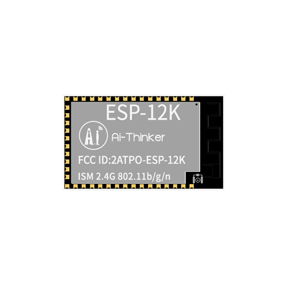
The ESP-12 module has a reasonably large number of pins exposed and has 4 MB Flash which proved necessary . Wifi is 2.5 Ghz b/g/n protocols only. The ESP-12F module uses a FCC certified and redesigned on-PCB antenna while the 12K module has an E-IF socket for an external antenna, if required.

Limitations of the ESP-12 module (but not unique to this module) is that
- module pin spacing is not breadboard friendly,
- requires 3.3V and a relatively high current source (up to 500 mA peaks), with no onboard power regulation and
- requires a serial interface like a FTDI board for flash programming.
The advantage of using the NodeMCU development board for prototying (V1.0 is based on ESP-12E) is that
- most pins are broken out in a breadboard-friendly pin spacing,
- NodeMCU has suitable onboard power regulation and allows board to be powered by 5V sources
- FTDI or similar programmer built-into the development board.
Given the CloudSmoker will be used outside my house, I purchased an external 2.4 GHz 3 DBI antenna in the event I need to improve WiFi reception.
- Form Color: Black + Gold
- Material: Alloy + Plastic
- Interface: PR-SMA
- Frequency Range: 2.3G - 2.5GHz
- Gain: 3
- Size: 11cm/4.3in, extension about 9cm/3.5in

ESP-12K has antenna mount
Note that the ESP-07 contains a zero-ohm SMD resistor to the on-module ceramic antenna that must be removed if the external antenna is to be use. Leaving both antennas functioning will result in poor impedance matching.
![]()