Flow Diagram of Project

- Provide a Writeup / README that includes all the rubric points and how you addressed each one. You can submit your writeup as markdown or pdf.
- Implement the method "matchBoundingBoxes", which takes as input both the previous and the current data frames and provides as output the ids of the matched regions of interest (i.e. the boxID property). Matches must be the ones with the highest number of keypoint correspondences.
3D_Object_Tracking/src/camFusion_Student.cpp
Line 317 in d172088
- Compute the time-to-collision in second for all matched 3D objects using only Lidar measurements from the matched bounding boxes between current and previous frame.
3D_Object_Tracking/src/camFusion_Student.cpp
Line 279 in d172088
- Prepare the TTC computation based on camera measurements by associating keypoint correspondences to the bounding boxes which enclose them. All matches which satisfy this condition must be added to a vector in the respective bounding box.
3D_Object_Tracking/src/camFusion_Student.cpp
Line 188 in d172088
- Compute the time-to-collision in second for all matched 3D objects using only keypoint correspondences from the matched bounding boxes between current and previous frame.
3D_Object_Tracking/src/camFusion_Student.cpp
Line 216 in d172088
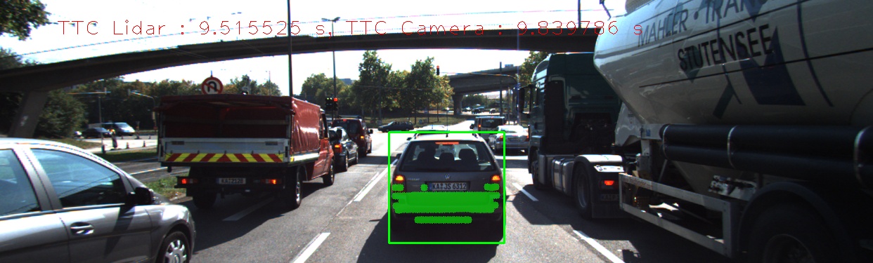
According to the above examples, It can be assumed that the factor that caused the lidar to be somewhat off compared to the Camera TTC is due to the outliers points. Even though we used the mean distance of all points between the current and previous frame. This was not enought to get rid of these outliers which affected our results. One way to solve this would be to lower the threshold value of what is acceptable when calculating TTC Lidar. Thus points that fall above the mean euclidian distance times the threshold will be ignored. Currently the threshold is set to 1.3 but one could lower it to 1.1 to get rid of more points that affect the lidar TTC calculation.


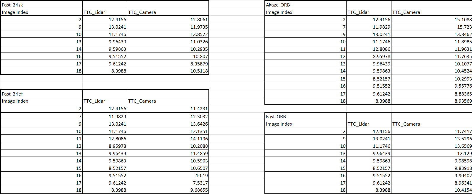
Graph of Chosen Detectors-Descriptors which shows the differences between TTC Lidar and TTC Camera estimation

Chosen Detector-Descriptor and TTC Lidar observation:
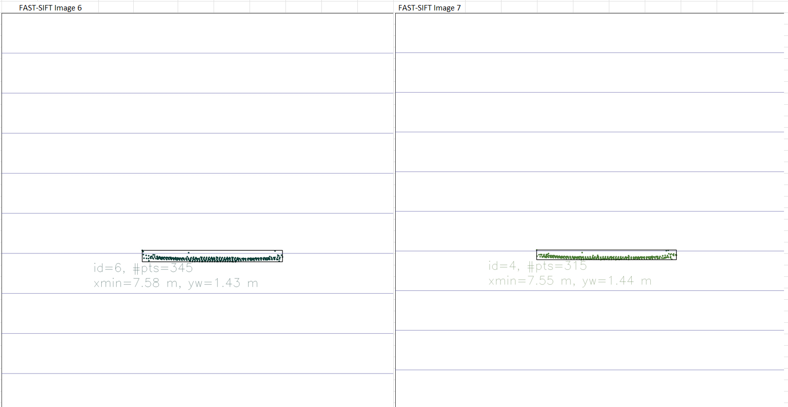
Fast-Brisk:
- Looking at the Fast-Brisk combination one can easily see that Image 9 the Lidar TTC estimation is off due to the amount of outliers in the image.
Fast-ORB:
- Looking at the Fast-ORB combination one can easily see that Image 10 the Lidar TTC estimation is off due to the amount of outliers in the image.
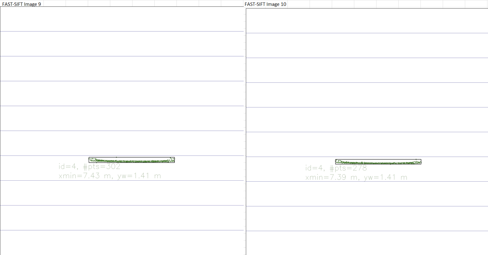
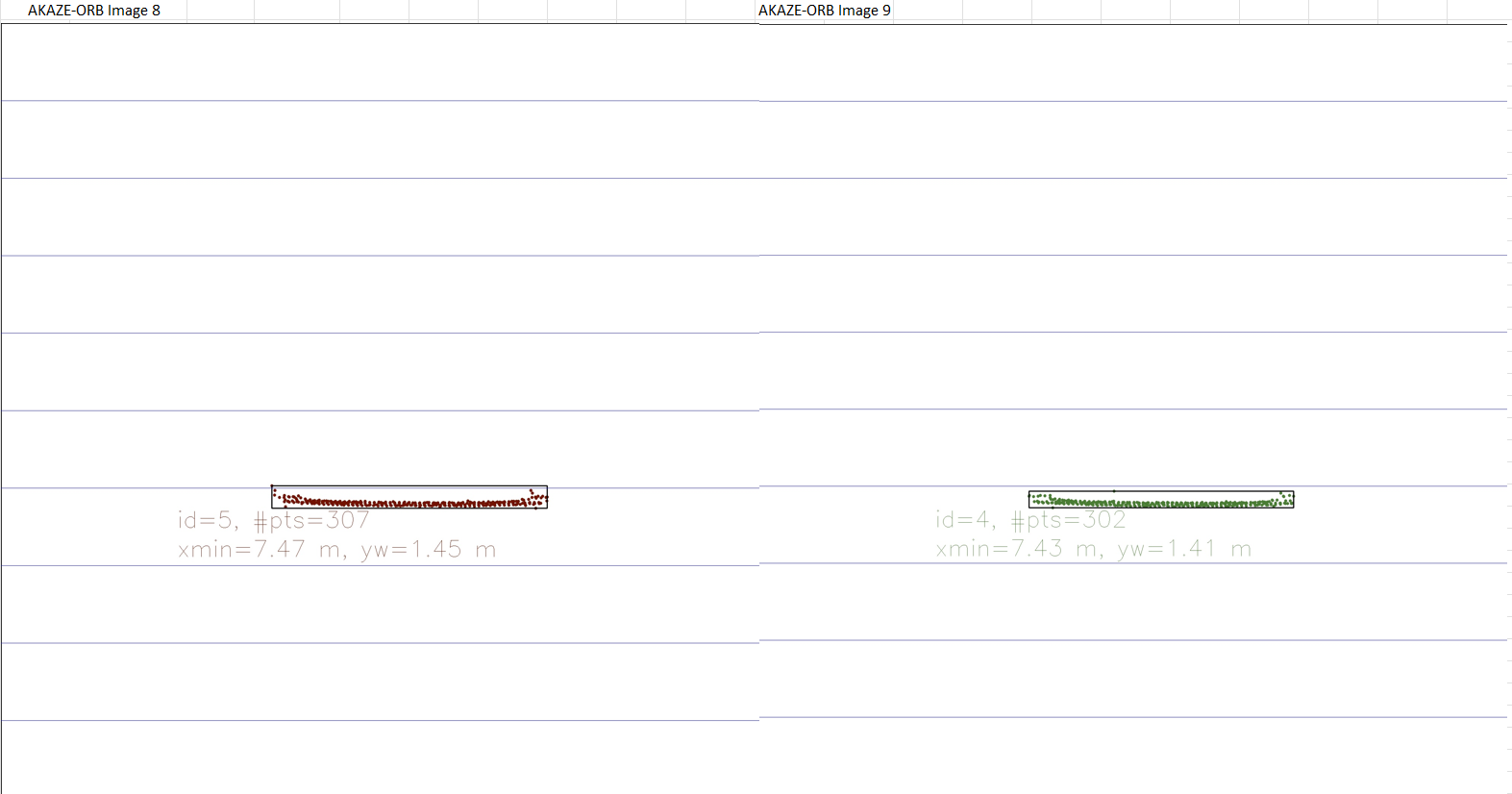
Akaze-ORB:
- Looking at the Akaze-ORB combination one can easily see that Image 9 the Lidar TTC estimation is off due to the amount of outliers in the image.
Fast-Brief:
- Looking at the Fast-Brief combination one can easily see that Image 10 the Lidar TTC estimation is off due to the amount of outliers in the image.
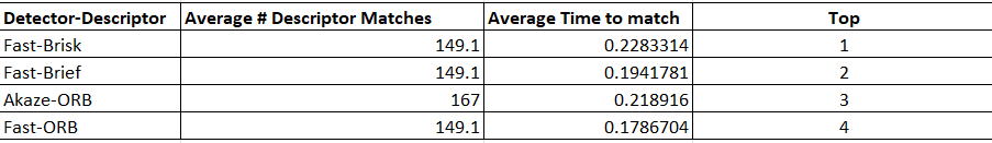
I chose the following 3 top detector/descriptor combinations because they are the ones that perform the fastest. Therefore my answer to this question is biased on the seed of the Combination of detectors/descriptors. The faster and more accurately we can obtain an estimated TTC then the better since in real life applications speed is important and reliability when talking about life and death scenarious.
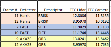
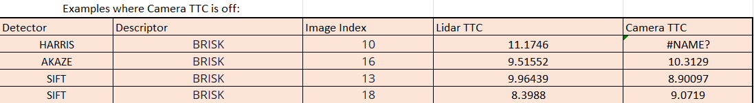
Below is a table which shows some examples where TTC Camera estimation is way off.
- In harris-brisk Image 10 Excel was unable to calculate or show the estimated TTC Camera since the value would have been infinity.
- cmake >= 2.8
- All OSes: click here for installation instructions
- make >= 4.1 (Linux, Mac), 3.81 (Windows)
- Linux: make is installed by default on most Linux distros
- Mac: install Xcode command line tools to get make
- Windows: Click here for installation instructions
- Git LFS
- Weight files are handled using LFS
- Install Git LFS before cloning this Repo.
- OpenCV >= 4.1
- This must be compiled from source using the
-D OPENCV_ENABLE_NONFREE=ONcmake flag for testing the SIFT and SURF detectors. - The OpenCV 4.1.0 source code can be found here
- This must be compiled from source using the
- gcc/g++ >= 5.4
- Linux: gcc / g++ is installed by default on most Linux distros
- Mac: same deal as make - install Xcode command line tools
- Windows: recommend using MinGW
- Clone this repo.
- Make a build directory in the top level project directory:
mkdir build && cd build - Compile:
cmake .. && make - Run it:
./3D_object_tracking.