Version: 2.4.0
Author: Roman Kiselev
License: Apache 2.0
URL: https://github.com/stjude-smc/microsync
Upload microsync-<x.y.z>.bin firmware file to Arduino Due (e.g. using BOSSA).
Install Python microsync module.
from microsync import SyncDevice

# Connect to device
sd = SyncDevice("COM4")  # or "/dev/ttyUSB0" on Linux

# Schedule a laser pulse
sd.pos_pulse("A0", 1000, ts=1000)  # 1ms pulse on A0 after 1ms delay
sd.go()  # Start execution
📖 Full Documentation | 📓 Interactive Demo
This project is a high-precision sync device for advanced microscope control, built around an Arduino Due (32-bit ARM Cortex-M3). It combines:
- Firmware (C++): Handles real-time event scheduling, pin control, and safety interlocks directly on the microcontroller. Uses a priority queue to manage up to 450 timed events (e.g., laser pulses, camera triggers) with microsecond accuracy.
- Python API: Lets you easily talk to the device, schedule events, and run complex acquisition protocols from your computer.
The device connects to your computer via UART (115,200 baud). All timing and pin logic runs on the microcontroller for reliable, low-latency operation.

Color legend: green – software components, yellow – microcontroller peripherals, purple – external hardware.
- Microsecond-precision event scheduling (pulses, toggles, pin set/reset, bursts)
- Priority event queue with hardware-timed execution
- Laser shutter and interlock safety logic
- Support for advanced acquisition modes (continuous, stroboscopic, ALEX)
- Comprehensive Python API with logging and context management
- Extensive examples and documentation in Jupyter notebook
- Platform: Arduino Due (32-bit SAM3X8E ARM Cortex-M3 microcontroller)
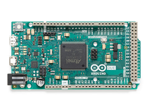
Arduino Due board - the hardware platform for microsync
- Key Pins:
- Laser shutters: A0 (Cy2), A1 (Cy3), A2 (Cy5), A3 (Cy7)
- Camera trigger: A12
- Error indicator: D53
- Interlock: D12 (input), D13 (output)
- Burst pulse: D5
- See
doc/Arduino Due pinout.pdfandmicrosync/src/globals.hfor full pin mapping.
Upload microsync-<x.y.z>.bin to your Arduino Due using BOSSA or Atmel-ICE with Microchip Studio.
- Download BOSSA from https://github.com/shumatech/BOSSA/releases (pick the right binary for your OS).
- Connect Due to your computer, use the USB port next to the power jack.
- Find newly created Arduino Due COM port (e.g. in the Device manager).
- On your Due, press Erase and Reset buttons at the same time (to enter programming mode).
- Run BOSSA GUI.
- Select the correct COM port.
- Select
microsync-<x.y.z>.binfile. - Important: Check the "Boot from Flash" option (this sets GPNVM0=1).
- Click "Write".
- Put
bossac.exe(orbossacon Mac/Linux) andmicrosync-<x.y.z>.binin the same folder. - Open a terminal in that folder and run (replace
<COM-PORT>with the actual COM port of your Due):
bossac.exe -e -w -v -b microsync-<x.y.z>.bin -p <COM-PORT>- Connect Atmel-ICE SAM connector to JTAG header on your Due.
- Connect Atmel-ICE to your computer.
- Power up your Due with a USB cable.
- Open Microchip Studio.
- Open the Device Programming dialog (Ctrl+Shift+P).
- Select Atmel-ICE tool,
ATSAM3X8Edevice, JTAG interface, click "Apply". - Go to "Memory" tab, select
microsync-{version}.binfile, click "Program".
Default Connections:
-
Laser shutters: Arduino pins A0-A3 (configurable in
globals.h) -
Camera trigger: Pin A12 (configurable)
-
USB connection: Provides both power and host communication via the micro-USB port next to the power socket. The device is powered through this USB connection and is recognized by the host computer as a virtual COM port.
-
Interlock circuit: D12 (input) and D13 (output) for laser safety
The device communicates via UART at 115,200 baud using a fixed-length 24-byte packet format. Each packet contains a command and associated parameters for precise event scheduling. All 24 bytes of a packet must arrive together, with no delay longer than 25 ms between individual bytes; otherwise, the packet is considered incomplete and will be discarded.

Packet Format:
- Command (4 bytes): 3-character command string, null-terminated
- Argument 1 (4 bytes): First parameter (pin index, duration, etc.)
- Argument 2 (4 bytes): Second parameter (additional settings)
- Timestamp (4 bytes): Scheduled time point of function call, in microseconds
- Count (4 bytes): Number of repetitions (0 = infinite)
- Interval (4 bytes): Time between repetitions in microseconds
Startup Message: Upon opening of the COM port, the device resets and sends the startup message the includes the firmware version.
Sync device is ready. Firmware version: 2.4.0
Requires Python 3.7+ and pyserial.
Install with:
pip install pyserialCopy the python/ directory or install as a package if desired.
The Python driver consists of several modules:
microsync.py- MainSyncDeviceclass and communication interfaceconstants.py- Timing constants and system parametersprops.py- Property definitions and system settingsrev_pin_map.py- Hardware pin mapping (Arduino pin names to internal IDs)__version__.py- Version information and package metadatasync device demo.ipynb- Comprehensive Jupyter notebook with examples
from microsync import SyncDevice

# Connect to the device (replace COM4 with your port)
sd = SyncDevice("COM4", log_file='print')  # log_file can be None, 'print', or a filename

# Get device status
print(sd.get_status())
print(sd.version)

# Set and get properties
print(sd.pulse_duration_us)
sd.pulse_duration_us = 1000

# Schedule a positive pulse on pin A0
sd.pos_pulse("A0", 8000, N=120, interval=50000)
sd.go()- Set
log_file='print'to print all communication. - Set
log_file='filename.log'to save to a file.
Batch multiple commands for precise timing: all commands within the context manager are collected and sent together as a single data packet over UART, ensuring they are processed together on the device. This approach eliminates timing jitter caused by delays or variability in the host operating system, resulting in highly accurate event scheduling.
with sd as dev:
    dev.pos_pulse("A12", 100000, N=10, interval=500000, ts=0)
dev.pos_pulse("A0", 100000, N=10, interval=500000, ts=5000)- Pulse:
sd.pos_pulse(pin, duration, ts, N, interval) - Toggle:
sd.tgl_pin(pin, ts, N, interval) - Set/Reset:
sd.set_pin(pin, level, ts, N, interval) - Enable/Disable Pin:
sd.enable_pin(pin),sd.disable_pin(pin) - Clear/Stop/Go:
sd.clear(),sd.stop(),sd.go()
The device uses a priority queue to manage event scheduling with microsecond precision. Each data packet received from the host is converted into an internal event structure for scheduling. The most significant change is the conversion of timestamp from 4-byte to 8-byte integer, as well as mapping of pins from name to internal IOPORT index.
Internal Event Structure (28 bytes):
- Function pointer (4 bytes) — what action to execute (
EventFunc func) - Argument 1 (4 bytes) — first parameter for the function (e.g., pin number)
- Argument 2 (4 bytes) — second parameter for the function (e.g., duration)
- Timestamp (8 bytes) — 64-bit absolute time when to execute (
ts64_cts) - Count (4 bytes) — number of repetitions remaining (
N) - Interval (4 bytes) — time between repetitions (
interv_cts)
Queue Operation:
- Packet Processing: 24-byte data packets are converted to 28-byte event structures
- Sorting: Events are automatically sorted by timestamp (earliest first)
- Execution: System timer triggers the next event at its exact timestamp
- Repetition: Events with
N > 1are rescheduled with updated timestamps - Precision: Hardware timer ensures microsecond-accurate execution
- Capacity: Up to 450 events can be queued simultaneously
Example: When you schedule multiple events, they're automatically ordered and executed in time sequence, regardless of the order they were submitted. If two events have exactly the same timestamp, their execution order is undefined.
- Open/Close shutters:
sd.open_shutters(mask),sd.close_shutters(mask) - Select lasers:
sd.selected_lasers = 0b0110(bitmask: Cy2, Cy3, Cy5, Cy7) - Interlock:
sd.interlock_enabled = True/False
The device includes a sophisticated laser safety interlock that monitors the integrity of the laser safety circuit:
Hardware Setup:
- Output pin (D13): Sends heartbeat pulses every 25ms
- Input pin (D12): Monitors return signal from interlock circuit
- External circuit: Required between D12 and D13 for proper operation
Operation:
- Heartbeat Generation: System sends pulse train on D13 (HIGH for 1.56ms, LOW for 23.44ms)
- Signal Monitoring: System checks D12 at two critical moments:
- When output goes LOW (should detect LOW on input)
- When output goes HIGH (should detect HIGH on input)
- Safety Logic:
- Normal: Both conditions met → Lasers enabled
- Fault: Either condition fails → Lasers immediately disabled
- Detects open circuits, short circuits, and missing connections
Runtime Control:
sd.interlock_enabled = True # set to False to ignore the interlock circuitIn practice, you want to have normally closed magnetic reed switches (such as Magnasphere) installed on the doors of the microscope enclosure, connected in series.
The following high-level acquisition modes are provided as convenience functions for our pTIRF microscopes. Internally, each mode schedules a sequence of low-level events using the common event execution engine described above. This allows you to easily run complex imaging protocols, while retaining precise timing and coordination under the hood:
- Use case: Continuous illumination with synchronous camera readout
- Method:
sd.start_continuous_acq(exp_time, N_frames, ts=0) - Behavior: Laser shutters remain open during entire acquisition, camera triggered at precise intervals
- First frame: Automatically discarded as it contains pre-acquisition noise
- Use case: Brief laser illumination during each camera exposure
- Method:
sd.start_stroboscopic_acq(exp_time, N_frames, ts=0, frame_period=0) - Behavior: Laser pulse synchronized with camera exposure, followed by readout period
- Timelapse: Optional waiting period between frames when
frame_period > 0
Note: For ALEX, select lasers by setting
sd.selected_lasersin Python (e.g.,sd.selected_lasers = 0b0110), or send aSETcommand with therw_SELECTED_LASERSproperty ID (from theSysPropsenum) over UART.
- Use case: Multi-spectral imaging with alternating laser illumination
- Method:
sd.start_ALEX_acq(exp_time, N_bursts, ts=0, burst_period=0) - Behavior: Bursts of frames, each illuminated by different laser channel
- Timelapse: Optional waiting period between bursts when
burst_period > 0
- Get all scheduled events:
sd.get_events(unit="us"|"ms") - Check frames left:
sd.N_frames_left()
Note: All timing parameters for microsync are specified in microseconds (µs).
Configure these timing parameters to match your hardware before starting acquisition:
# Essential timing parameters (in microseconds)
sd.shutter_delay_us = 1300      # Laser shutter opening time
sd.cam_readout_us = 14000       # Camera readout duration (depends on ROI)
sd.pulse_duration_us = 800      # Default pulse duration

# Laser selection (bitmask: Cy2=bit0, Cy3=bit1, Cy5=bit2, Cy7=bit3)
sd.selected_lasers = 0b0110     # Enable Cy3 and Cy5 lasers
Important Notes:
shutter_delay_usshould match your laser shutter's actual opening time. Use an oscilloscope and a photodiode to measure it.cam_readout_usdepends on camera ROI settings. See the camera manual to find out how to calculate or query it.- Timing values persist between acquisitions until changed. They drop back to defaults after system reset.
See python/sync device demo.ipynb for a comprehensive, step-by-step tutorial with code, explanations, and advanced usage patterns.
| ID | Property | Access | Description |
|---|---|---|---|
| 0 | version |
Read-only | Firmware version |
| 1 | running |
Read-only | System timer running status |
| 2 | sys_timer_value |
Read-only | System timer value (counter ticks) |
| 3 | sys_timer_ovf_count |
Read-only | System timer overflow count |
| 4 | sys_time_ms |
Read-only | System time (milliseconds) |
| 5 | prescaler |
Read-only | System timer prescaler |
| 6 | pulse_duration_us |
R/W | Default pulse duration (microseconds) |
| 7 | watchdog_timeout_ms |
Read-only | Watchdog timeout (ms) |
| 8 | N_events |
Read-only | Number of events in queue |
| 9 | interlock_enabled |
R/W | Laser interlock state (0=disabled) |
| 10 | selected_lasers |
R/W | Bitmask of enabled laser channels |
| 11 | open_shutters |
Write-only | Open specified laser shutters |
| 12 | close_shutters |
Write-only | Close specified laser shutters |
| 13 | shutter_delay_us |
R/W | Shutter delay (microseconds) |
| 14 | cam_readout_us |
R/W | Camera readout time (microseconds) |
📖 Full Documentation - Complete API reference, user guides, and examples
- Firmware: See
microsync/src/for C++ source and hardware logic. - Python API: See
python/microsync.pyand the Jupyter notebook. - Data packet structure: See
doc/data packet structure.xlsx.
This project includes comprehensive Sphinx/Doxygen documentation that combines Python API documentation with C++ firmware documentation.
Doxygen: Required for C++ documentation generation
- Windows: Download and install from Doxygen website
- Linux:
sudo apt-get install doxygen(Ubuntu/Debian) orsudo yum install doxygen(CentOS/RHEL) - macOS:
brew install doxygen
Run the automated build script from the project root:
python build_docs.pyThe documentation will be available at sphinx_docs/_build/html/index.html. The generated documentation includes:
- Python API Reference: Auto-generated from docstrings in the Python modules
- C++ API Reference: Generated from firmware header files using Doxygen + Breathe
- User Guide: Manual documentation and examples
- Firmware Architecture: Detailed explanations of the C++ implementation
The Sphinx documentation automatically builds and deploys to GitHub pages on every push to branches develop and master via GitHub actions.
The firmware is built using Microchip Studio or compatible IDEs:
- Open the project: Load
microsync.atslnin Microchip Studio - Build target: Select "Release" configuration
- Upload: Use the Atmel ICE debugger, connected via JTAG interface to the microcontroller board. Hit
Ctrl+Shift+Pto open the programming dialog. - Debugging: If you upload the "Debug" configuration, you can set a breakpoint and pause the code execution on Arduino Due when it's connected via JTAG to Atmel ICE. You will have a normal step-by-step debugging with the direct access to the device registers and memory via Microchip Studio . The caveat is that the hardware timers keep running while you're in the debug mode. Use an oscilloscope when verifying event order and timing in addition to the code debugging.
main.cpp: Entry point and system initializationglobals.h: Global definitions, pin mappings, and system settingsevents.h/cpp: Event scheduling and priority queue managementuart_comm.h/cpp: Communication protocol implementationpins.h/cpp: Pin control and hardware abstractioninterlock.h/cpp: Laser safety interlock logic (can be disabled)
- Event queue: Maximum 450 scheduled events (vs. 4 hardware timers in legacy)
- Jitter: Events scheduled within ~10µs of each other may have timing jitter
- Overload protection: A watchdog timer automatically resets the system if event queue overflows
- Interlock: Requires external circuit between D12 and D13 for laser safety
- External triggers: Not available yet, but possible to add. In the future, we could make it so the device reacts to changes on an input pin (like a button press or signal) and schedules events automatically.
Note: These limitations are significantly improved compared to the legacy 8-bit version, which had 4.19s exposure limits and 64µs timing resolution.
This is the second generation of the microscope synchronization device, based on a 32-bit ARM microcontroller (Arduino Due). The first generation was based on Arduino Mega2560 (8-bit ATMega2560) and had fundamental limitations:
Key Changes and Improvements in 32-bit Version:
- 3.3V logic – Arduino Due uses 3.3V CMOS logic levels for digital I/O, whereas the Arduino Mega2560 uses 5V logic levels
- Microsecond precision (vs. 64µs steps in 8-bit version)
- No 4.19s exposure time limit (vs. 16-bit timer limitation)
- Event-driven architecture with priority queue (vs. fixed state machine)
- Up to 450 scheduled events (vs. limited to 4 hardware timers)
- Advanced acquisition modes with precise timing control
- Safety interlocks for laser protection
- Modern Python API with context management and logging
Legacy Repository: The original 8-bit version is available at sync_device_8bit_legacy for reference.
Apache 2.0.
(c) Roman Kiselev, St. Jude Children's Research Hospital
- Based on Atmel SAM3X8E microcontroller (Arduino Due board)
- Uses
ASF(Atmel Software Framework) - See
/docfor datasheets and pinouts
For questions or contributions, please open an issue or pull request on GitHub.