![]()
![]()


- Loud-ESP development board
- Hardware
- Firmware
Loud-ESP Kits is a set of development boards designed to make audio development for the ESP platform easy and feature-rich.
Key properties of this kit
- It uses ESP chips as an MCU core, which has a huge community support and adaptation
- It delivers 2-channel amplified high-quality audio ready to be connected to speakers of choice - no need to have an external amplifier. Therefore, it is all you need to complete your audio projects
- It has low idle power consumption and built-in Li-Ion battery management; therefore, it is a good choice for any sort of portable and portable audio projects.
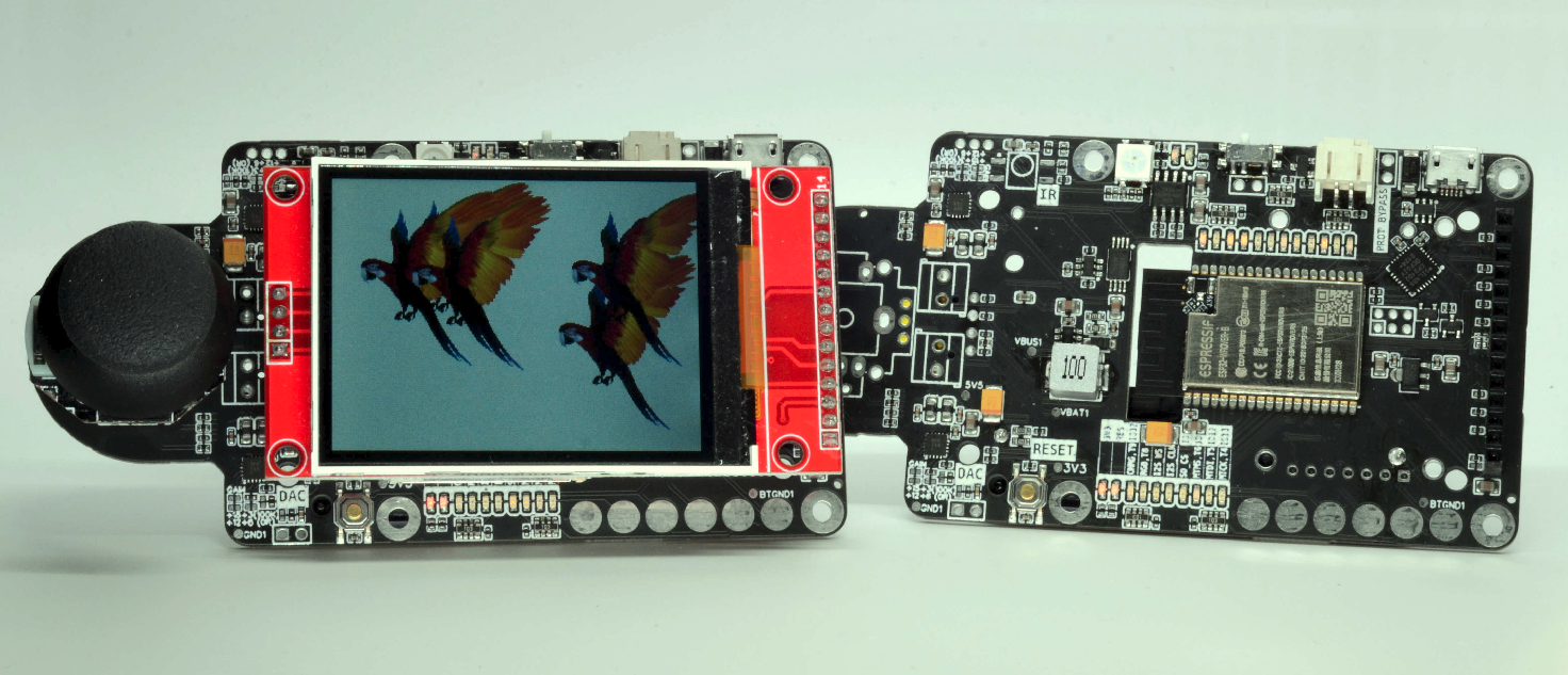
- It has a rich UX peripheral, most obviously a TFT screen with touch, but also an IR receiver, and a header for physical controls, like a rotary encoder or joystick. Therefore, it is a good choice for standalone user-facing audio projects.
As of autumn 2025, I'm working on a spin-off of the original board that is tailored specifically for Espuino firmware, with a key difference to the original board being a replacement of the TFT screen with an RFID reader. It can be used for offline RFID-controlled media player devices, although I personally found it most usable in connection with Home Assistant and ESPHome driver integration.
While working on the new revision of the board, both received a few major schematic improvements to address a few issues I found over time with the original design. These include
- New 3.3V buck-boost IC (TPS63060DSCR) that better handles low battery state
- SDIO interface for the SD-card (as opposed to SPI, it uses fewer pins and provides better speed)
- Move to the CH340C serial chip, as it seems more robust compared to the CP2102
- Better power switch and a few smaller improvements.

MCU Core
- ESP32 Dual Core 32-bit LX6 microprocessor running at 240 MHz
- 16MB of flash storage
- 8MB of PSRAM
- CP2102/CH340C Serial communication/ Flashing chip
Battery management
- Li-Ion battery charging with charge status indication
- Battery overcharge and over-discharge protection
- Battery overcurrent protection
- Onboard 14500 battery holder or 2-pin connector for external battery (except Mini version)
- Battery voltage reading using built-in DAC
- Onboard power switch
Audio capabilities
- Dual I2S stereo DAC (MAX98537) with built-in D-Class amp
- 3W per channel on 4 Ohm load
- Up to 92% efficiency
- Onboard 5V boost converter
Peripheral
- 2.8'' 320x240 TFT Screen with Touch sensor (except Mini version)
- Wifi and BT
- IR reader (except the Mini version)
- RGB LED, RGB LED strip header
- SDCard socket (except Mini version)
- JTAG header (except the Mini version)
- Rotary encoder/Joystick header (except the Mini version)
Other
- RESET and GPIO0 (FLASH) buttons
- Raspberry Pi 4 case mechanical compatibility
- Software samples for every piece of onboard peripheral

Compared to the original board, this one clearly changed shape to be hosted in the speaker enclosure. Apart from that, changes include
MCU, Audio, and Battery management
- Same as Loud-ESP
Peripheral
- RFID reader
- RGB LED bar (12 LEDs)
- SDCard socket (except Mini version)
- Onboard rotary encoder with push button
- 5x Push-buttons connected via GPIO expander
- 1x Push-button (instead of a slide switch) to cut off power while not in use
Prototype
Latest board
| Assembed | PCB only |
|---|---|
 |
 |
| IMAGE | DESCRIPTION |
|---|---|
 |
 MCU (WROVER ESP32) MCU (WROVER ESP32)  RESET and IO0/FLASH buttons RESET and IO0/FLASH buttons  Speaker Terminals Speaker Terminals  Li-Ion Battery Connector Li-Ion Battery Connector  Power switch Power switch  USB port (Flashing + Serial + Power + Charging) USB port (Flashing + Serial + Power + Charging)  RGB LED RGB LED  5V Boost converter 5V Boost converter |
| IMAGE | DESCRIPTION |
|---|---|
 |
MCU (WROVER ESP32) RESET and IO0/FLASH buttons Speaker Terminals Li-Ion Battery Connector Power switch USB port (Flashing + Serial + Power + Charging) RGB LED Dual 5V Boost converter  IR Sensor IR Sensor  TFT Screen Connector TFT Screen Connector  SD Card socket SD Card socket  Rotary Encoder/Joystick module conector Rotary Encoder/Joystick module conector |
| IMAGE | DESCRIPTION |
|---|---|
 |
 External RGB Strip connector. Chained to built-in RGB LED External RGB Strip connector. Chained to built-in RGB LED  External Power switch. Short via the external button to power on the board. External Power switch. Short via the external button to power on the board.  External 5V source. Alternative source of power and charging External 5V source. Alternative source of power and charging  Disable battery current protection jumper. Short to override built-in 2A current limiter (only if you know what you're doing) Disable battery current protection jumper. Short to override built-in 2A current limiter (only if you know what you're doing) |
Both Boards have jumpers that can be used to configure the gain factor individually for both channels. The default GAIN is +9 dB. Short appropriate jumper to override the default To hardwire the DAC into MONO mode, you need to cut the MONO jumper (it is short by default)
| Loud-ESP MINI | Loud-ESP |
|---|---|
 |
 |
These boards come in multiple revisions; normally, the revision of the specific board will be clearly visible on the back side of the PCB.

The current distribution of board revisions looks like this
| Revision | Loud-ESP | Revision | Loud-ESP Mini | Description |
|---|---|---|---|---|
| D |  |
- | Extended PCB with built-in Rotary Encoder/ Joystick | |
| E |  |
E |  |
Pre-production prototype. Distributed among beta-testers |
| F |  |
F |  |
Crowd Supply distribution |
| G |  |
- | - | Engineering sample that replace serial bridge with CH340 (due to few CP2102 failures reported by customers) |
| H |  |
- | - | Recent board update, introduce improved power topology, CH340 Serial bridge, USB-C port, and SDCARD over SDIO interface. |
Reviosions A, B, and C were early prototypes, never distributed due to multiple hardware issues.

| PIN | PRIMARY FUNC | JTAG | I2S | TFT | TOUCH_TFT | RGB_LED | BAT | IR | SDCARD | ROTARY ENC/ BTN INP | PSRAM |
|---|---|---|---|---|---|---|---|---|---|---|---|
| IO0 | BOOT SEL | IR_IN | |||||||||
| IO1 | TX | ||||||||||
| IO2 | CS | ||||||||||
| IO3 | RX | ||||||||||
| IO4 | DC | ||||||||||
| IO5 | VSPI_CS | CS | |||||||||
| IO12 | HSPI_MISO | MTDI | |||||||||
| IO13 | HSPI_MOSI | MTCK | |||||||||
| IO14 | HSPI_CLK | MTMS | |||||||||
| IO15 | HSPI_CS | MTDO | |||||||||
| IO16 | PSRAM_CS | ||||||||||
| IO17 | PSRAM_CLK | ||||||||||
| IO18 | VSPI_CLK | CLK | CLK | CLK | |||||||
| IO19 | VSPI_MISO | MISO | MISO | MISO | |||||||
| IO21 | CHRG | ||||||||||
| IO22 | DATA | ||||||||||
| IO23 | VSPI_MOSI | MOSI | MOSI | MOSI | |||||||
| IO25 | WS | ||||||||||
| IO26 | CLK | ||||||||||
| IO27 | CS | ||||||||||
| IO32 | RES/LED | ||||||||||
| IO33 | OUT | ||||||||||
| IO34 | BAT_IN | ||||||||||
| IO35 | A | ||||||||||
| IO36 | B | ||||||||||
| IO39 | BTN |
Key hardware updates introduced in the rev H
- SD-CARD over SDIo interface
- CH340 Serial chip instead of CP2102
- Few people reported its failure
- USB-C instead of mini-USB
- TPS63060 step-up/step-down 3.3V converter, which ensures smooth operation with low battery levels
- Previous revision started flickering when battery voltage goes low, since the 3V3 rail would go even below 3V, causing ESP32 brown-outs
Having used Loud-ESP for a few projects involving SDCARD, I came to the idea that having 3 high-speed devices on the same SPI line is not the best approach. Since SD-CARD can alternatively be connected to the SDIO interface, I decided to follow that path in revision H.
SDIO interface is hardwired to pins IO2, IO4, IO12-15, and by the SD specification, all must be pulled high for reliable operation. At the same time, the ESP32 specification states that pins 2 and 12 must be low at boot, otherwise the ESP32 will go into download mode. Thus, I left them floating, which caused some SD cards to fail. I didn't find a reliable solution to this contradiction and consider going back to the SPI interface in the next revision.
| PIN | PRIMARY FUNC | JTAG | I2S | TFT | TOUCH_TFT | RGB_LED | BAT | IR | SDCARD | ROTARY ENC/ BTN INP | PSRAM |
|---|---|---|---|---|---|---|---|---|---|---|---|
| IO0 | BOOT SEL | IR_IN | |||||||||
| IO1 | TX | ||||||||||
| IO2 | D0 | ||||||||||
| IO3 | RX | ||||||||||
| IO4 | D1 | ||||||||||
| IO5 | VSPI_CS | CS | |||||||||
| IO12 | HSPI_MISO | MTDI | D2 | ||||||||
| IO13 | HSPI_MOSI | MTCK | D3 | ||||||||
| IO14 | HSPI_CLK | MTMS | CLK | ||||||||
| IO15 | HSPI_CS | MTDO | CMD | ||||||||
| IO16 | PSRAM_CS | ||||||||||
| IO17 | PSRAM_CLK | ||||||||||
| IO18 | VSPI_CLK | CLK | CLK | CLK | |||||||
| IO19 | VSPI_MISO | MISO | MISO | MISO | |||||||
| IO21 | DC | ||||||||||
| IO22 | DATA | ||||||||||
| IO23 | VSPI_MOSI | MOSI | MOSI | MOSI | |||||||
| IO25 | WS | ||||||||||
| IO26 | CLK | ||||||||||
| IO27 | CS | ||||||||||
| IO32 | LED | ||||||||||
| IO33 | OUT | ||||||||||
| IO34 | B | ||||||||||
| IO35 | A | ||||||||||
| IO36 | BTN | ||||||||||
| IO39 | HOST |
esp32-peripheral-test firmware demonstrates how to use each of available peripheral. For many of them, you would need libraries, which are also included in this example. Of course, many alternatives can be found; for example, we will list those that are tested and work without a hassle.
Most repos are Platformio projects, all tested under Ubuntu 20.04 LTS. Some are ESP IDF projects, and would require installation steps before build
Most of the repos will utilize multiple environments with different settings for different board revisions. Please refer to platformio.ini file within the project folder.
For each project, please find a detailed description using links below
- esp32-soundboard - singing birds sound board
- test-audio
- esp32-esp8266-audio-test-eeprom - play audio from EEPROM example
- esp32-esp8266-audio-test-sdcard-random - play audio files from sd-card
- esp32-esp8266-audio-test-spiffs - play audio from SPIFFS in loop example
- esp32-esp8266-audio-test-spiffs-once - play audio from SPIFFS once example
- esp32-esp8266-audio-test-spiffs-random - play audio from SPIFFS randomly example
- esp32-esp8266-audio-test-stream - play audio from internet stream
- esp32-esp8266-audio-test-stream-web - play audio from internet stream with web UI
- esp32-esp8266-wifi-radio-station - adaptation of VolosR/TTGOInternetStation repo
- esp32-esp8266-talking-clock - Talking clock mini project
- esp32-esp8266-text-to-speach-sam - Offline text to speach generation via SAM
- esp32-i2s-bare - audio generation using bare I2S sampling
- test-peripheral
- esp32-arduinomenu - example using ArduinoMenu library with rotary encoder and joystick
- esp32-arduinomenu-dynamic - same as above but with runtime built menu
- esp32-peripheral-test - test firmware that checks all available peripheral
- esp32-test-battery - example reading battery voltage and charge status
- esp32-test-sdcard - test reading files from SDCARD
- esp32-test-sleep-by-pin - sleep mode with button triggered wake up
- esp32-test-sleep-by-timer - sleep mode with timer wake up
- esp32-test-touch-pins - test reading built-in touch sensors on pins
- esp32-test-touch-screen - test TFT touch sensor
- test-visual
- esp32-demo-ir-volume - demo of using IR controller to change volume
- esp32-demo-visualisations - port of classic visualisations
- esp32-demo-vu-meters - demo of VU meters rendered on the screen
- esp32-esp8266-adafruit-spi-display-test - TFT example using Adafruit library
- esp32-esp8266-spi-display-test - TFT example using TFT_eSPI library
- esp32-test-lvgl - LVGL usage example
- squeezelite-esp32 - LMS, Airplay, Spotify-Connect
- can be installed via dedicated web-installer
- Ka-Radio32 - Web-Radio player with UI and physical controls
- ESP32-MiniWebRadio - also Web-Radio player with nice UI
- ESP32_MP3_Decoder - Also Web-Radio player (more basic setup)
- esp32-esp8266-weather-station and esp32-esp8266-weather-station-color - forks of the ThingPulse projects
- esp32-esp8266-screensavers - Classic screensavers on ESP32
Whenever repo is a Platformio project, it is preferred to use it to flash firmware to the board. platformio.ini file will contain specific sections for different board revisions and configurations. Hardware-specific details are preferred to keep in this file as well.
[env:esp32-dev-board-c-240x240]
platform = espressif32
board = esp32dev
framework = arduino
build_flags =
  -D USER_SETUP_LOADED=1
  -D ST7789_DRIVER
  -D TFT_WIDTH=240
  -D TFT_HEIGHT=240
  -D TFT_DC=27
  -D TFT_BL=26
  -D TFT_INVERSION_ON=1
  -D TFT_RGB_ORDER=TFT_BGR
  -D TFT_ROTATION=2

[env:esp32-dev-board-c-240x320]
platform = espressif32
board = esp32dev
build_flags =
  -D USER_SETUP_LOADED=1
  -D ST7789_DRIVER
  -D TFT_WIDTH=240
  -D TFT_HEIGHT=320
  -D TFT_DC=13
  -D TFT_CS=05
  -D TFT_BL=12
  -D TFT_INVERSION_OFF=1
  -D TFT_RGB_ORDER=TFT_BGR
  -D TFT_ROTATION=1
Follow the ESP8266Audio library guide. Default settings will work out of the box with both Loud-ESP and Loud-ESP Mini boards.
Being an ESP32-based device, you can easily integrate it into your Home Assistant using ESPHome. Start with esphome web installer, which will give you an ESPHome base install and WiFi configuration in minutes.
 |
 |
Next, navigate to your Home Assistant (assuming you have your ESPHome integration installed), and adopt the newly created node

ESPHome will give you ESPHome configs for both the mini and full versions of the board.
The loud-esp-mini config enables common board peripheral
media_playerpublishes the media player into the Home Assistant, so you can use it together with the native player or Music Assistant. You have a volume knob in the HA as well.
- Volume set up to 50% on player start. You can change that
lightcomponent exposes onboard RGB LED for use in integrations. In this example, it lights an LED depending on themedia_playerstatepsramenabled for all devices to smooth out playback
The loud-esp config enables all the board peripheral
remote_receiverexposes the IR reader. Example configures the SAMSUNG TV remote to control volume using volume buttons.displaycomponent configures the onboard displaytouchscreencomponent configures the onboard touchscreen and dumps touches to the console
The loud-esp-mopidy-monitor config is a project that I did myself for HA Mopidy media center integration
media_playercan be used for voice announcementsdisplayshows the current Mopidy playing item, Artist, and title.- three playback buttons allow Play/Pause track and move back and forward along the playlist via
touchscreencontrols - on the top of
display, there is a volume indicator with two buttons to change it - The progress bar shows the current progress of the track
displayalso shows playlist progress on the bottom with the current item highlighted

Currently, there is no component that can display track images, but it seems like it will be added soon
The true power of the native speaker in the eHA is the use of automation. One example that I find useful. This simple automation will be pronounced every hour between 8 AM and 9 PM. Another one is used to pronounce bedtime, you get the point...

Squeezelite-ESP32 is a multimedia software suite that started as a renderer (or player) of LMS (Logitech Media Server). Now it is extended with
- Spotify over-the-air player using SpotifyConnect (thanks to cspot)
- AirPlay controller (iPhone, iTunes ...) and enjoy synchronization multiroom as well (although it's AirPlay 1 only)
- Traditional Bluetooth device (iPhone, Android)
And LMS itself
- Streams your local music and connects to all major online music providers (Spotify, Deezer, Tidal, Qobuz) using Logitech Media Server - a.k.a LMS with multi-room audio synchronization.
- LMS can be extended by numerous plugins and can be controlled using a Web browser or dedicated applications (iPhone, Android).
- It can also send audio to UPnP, Sonos, Chromecast, and AirPlay speakers/devices.
All ESP32-based boards are tested with Squeezelite-ESP32 software, which can be flashed using nothing but a web browser. You can use Squeezelite-ESP32 installer for that purpose.
Use Installer for ESP Audio Dock to flash firmware first. It has been preconfigured to work with ESP Audio boards and will configure all hardware automatically.
| Select the correct device first |  |
| Connect the device to the USB port and select it from the list |  |
Press Flash and wait around 2 minutes |
 |
| (Optional) You may enter the serial console to get more information |  |
Device is in recovery mode. Connect to squeezelite-299fac wifi network with squeezelite password (your network name suffix will be different) |
 |
| When redirected to the captive portal let the device scan wifi network and provide valid credentials |    |
| You can use provided IP address (http://192.168.1.99/ on the screenshot) to access settings page |  |
| (Optional) You may change device names to something close to your heart |  |
| Exit recovery |  |
You can use it now
| Bluetooth | Spotify Connect | AirPlay | LMS Renderer |
|---|---|---|---|
 |
 |
 |
 |
You may support our work by ordering this product at Tindie and Elecrow