Inspired by the good old conventional Lego train speed regulator (2868), I made this design for controlling Lego PF Motors. It is based on an Arduino ProMini (or clone) and has a DRV8833 Motor driver module, a Rotary encoder and a 16 LED Neopixel Ring as forward/reverse speedindicator.

The conventional train regulator gives a analog 0-9V output signal. In this design, the PF motor is controlled with a Pulse Width Modulation (PWM) output signal. This means that the motor speed is controlled by varying the duty cycle of a square wave signal.
Earlier I made another version of a Lego speed controller based on the well known NE555 timer-IC.
For the MCU modules both the Arduino ProMini and the LGT8F328P LQFP32 MiniEVB (Pro Mini Style) can be used or even the LGT8F328P SSOP20 MiniEVB (pseudo Pro Mini Style).

You can buy the LGT8F328P MiniEVB modules on AliExpress very cheap.
I used the 5V version, because not all types of Neopixels are compatible with 3V3.
Furthermore, I use, among other things;
- A DRV8833 Motor driver module
- A Neopixel ring with 16 LEDs
- An EC11 Rotary encoder with push button

The design is made in KiCad 9.0 and is straight forward.
It can be powered by, for example, a 9V Lego battery box (8881) or by an external 9Vdc power adapter.
I first tested it in a breadboard setup.

I designed a 76x100mm PCB, which I ordered from JLCPCB.

The pcb design takes into account the footprint of the different MCU modules, however only 1 of the MCU modules needs to be placed.

The PCB 1.0 has this issue #1.
This is fixed in v1.1
On AliExpress you can buy PF connectors and 4 core wire and make your own Lego PF connection cables.
Before assembling the Input PF cable (connected to J11 in the schematic), I removed the C1 and C2 contacts from the Bottom part of the connector so that this connector can be used to connect both the battery box (via the 0V and 9V contacts in the BOTTOM part) as the Lego PF-motor as well (via the C1 and C2 contacts in the TOP part).

The output PF cable (connected to J13 in the schematic) is not modified (so has all its contacts).
So the PF-motor can be connected or to the input connector (connected to the Battery box) or to the output connector.
See this article about the working of de LEGO Power Function cable.
To upload the sketch from your computer into the Arduino board you will need a FTDI USB to TTL Adapter.

Then;
- Install the following libraries:
- lgt8fx library (When you use a LGT8F328P MiniEVB Board)
- Neopixel library
- Rotary library
- Download the sketch (You can also download the the sketch from my github)
- Set the proper board settings (see picture below for the LGT8F328P board settings) and upload the sketch

For clarification;
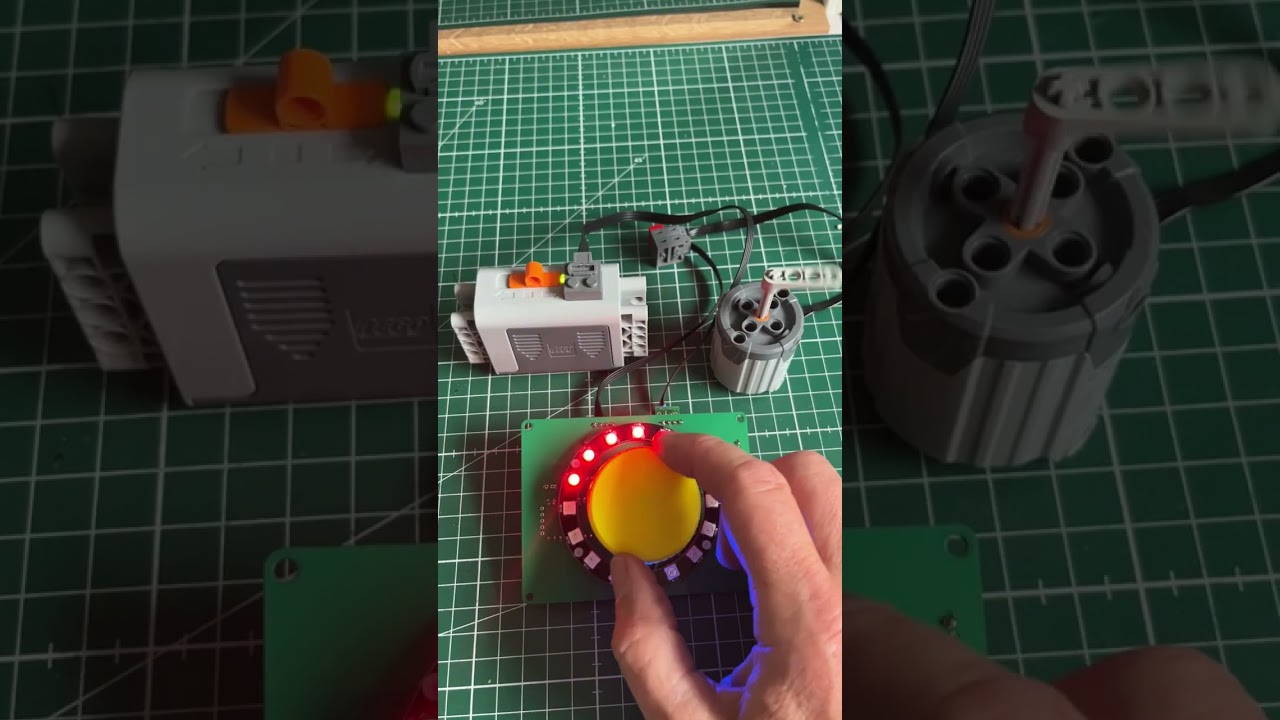
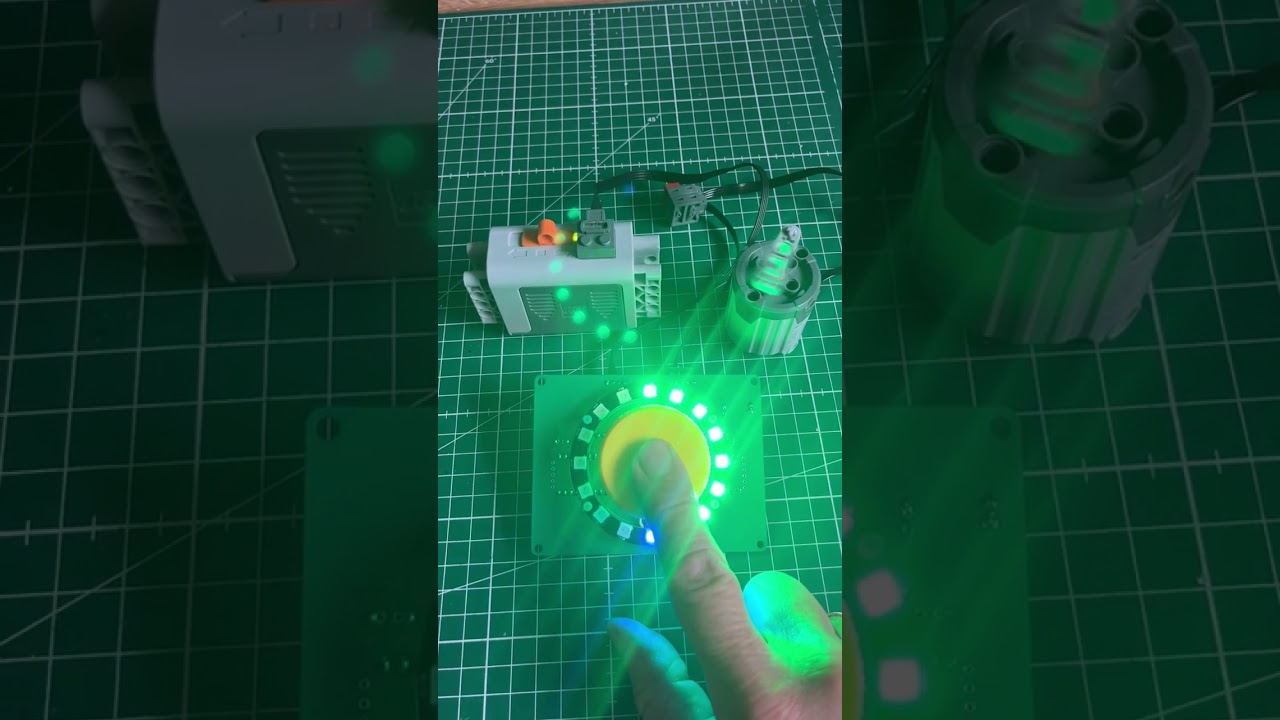
- The Neopixel ring indicates the output signal (similar to the big yellow button on the conventional Lego train speed regulator).
- Turning the Rotary encoder knob to the right wll increase the speed in forward direction (Green color), turning to the left will decrease the speed to 0 (LED8 is the center of the indication scale) and then increases the speed in reverse direction (Red color).
- Neopixel LED0 is set to blue as power-on indication.
- When your Rotary encoder is equipped with a push button; a short button press will increase the brightness of the LEDs (in 9 steps) and a long button press (>2sec) will reset the brightness to the default 10% and set the speed to 0 (Stop).
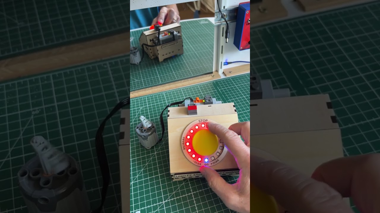
And this is what it looks like when assembled

Watch the video's
I designed a big 45mm knob in FreeCad (v1.0) for the Rotary encoder and 3d printed it in yellow
The design is parametric - the knob dimensions can be modified in the spreadsheet tab

The enclosure is a clever lasercut design from this site with lots of boxes. It is based on this console and has a small box on the back for the Battery box.
Then I imported the svg output files into the lasercutter software (XTool) and made cutouts for the neopixel ring LEDs and the other things. The labels on the parts come on the inside of the box.

The holes in the front panel for the neopixel ring LEDs were reworked with a dremel tool to mill out the screws and smd resistors.

Assembling the box


Watch the video
For a guide on how to build this project, check out the tutorial at Instructables.