- Modeling in fusion 360 and Converting into URDF file to run in GAZEBO simulator.
- Gazebo Plugins
- Intro to R-viz and RQT graphs
- SLAM (Simultaneous localization and mapping)
- Navigation Stack to Self-design robot
Run the following command in your shell.
cd <path to fusion2urdf>
Copy-Item ".\URDF_Exporter\" -Destination "${env:APPDATA}\Autodesk\Autodesk Fusion 360\API\Scripts\" -RecurseThis is a fusion 360 script to export urdf from fusion 360 directly.
This exports:
- .urdf file of your model
- .launch and .yaml files to simulate your robot on the gazebo
- .stl files of your model
• I used fusion 360 software for designing and developing the robot and then that design model has been converted into a URDF file.


Adding the laser scan plugin to your robot can give it a sense of perception of the surrounding world. It simulates a Lidar on top of your robot. Open your exported URDF file, and navigate to the robot.gazebo file and add the plugin there.
<gazebo reference="hokuyo_link">
    <sensor type="gpu_ray" name="head_hokuyo_sensor">
      <pose>0 0 0 0 0 0</pose>
      <visualize>false</visualize>
      <update_rate>40</update_rate>
      <ray>
        <scan>
          <horizontal>
            <samples>720</samples>
            <resolution>1</resolution>
            <min_angle>-1.570796</min_angle>
            <max_angle>1.570796</max_angle>
          </horizontal>
        </scan>
        <range>
          <min>0.10</min>
          <max>30.0</max>
          <resolution>0.01</resolution>
        </range>
        <noise>
          <type>gaussian</type>
          <!-- Noise parameters based on published spec for Hokuyo laser
               achieving "+-30mm" accuracy at range < 10m.  A mean of 0.0m and
               stddev of 0.01m will put 99.7% of samples within 0.03m of the true
               reading. -->
          <mean>0.0</mean>
          <stddev>0.01</stddev>
        </noise>
      </ray>
      <plugin name="gazebo_ros_head_hokuyo_controller" filename="libgazebo_ros_gpu_laser.so">
        <topicName>/rrbot/laser/scan</topicName>
        <frameName>hokuyo_link</frameName>
      </plugin>
    </sensor>
  </gazebo>
As this is a standard plugin, we have to change a few parameters to make it work with our robot.
-
Change in the reference
The reference provided to the plugin is to be changed to the appropriate lidar_link_name. The lidar_link_name for your robot can be found in the robot.xacro file.
-
Frame Name for Laser
Goto the frameName section, and change the link name from hokuyo_link to the lidar_link_name previously found for the reference section
-
Setting the Laser angular range
In the range section of the plugin, the minimum and maximum angles (in radians) can be changed according to the expected angular range.
-
Topic Name for Laser
The plugin will publish the point cloud data obtained from the lidar to a topic of our choice. We can conveniently change the topic name to /scan for ease of access later. Goto the topicName section and change the topic name from ‘/rrbot/laser/scan’ to ‘/scan’
-
Removing the GPU usage
As we are going to use our CPU instead of a dedicated GPU to handle the computing for our Laser Plugin we have to remove the GPU keyword. The GPU keyword has to be removed from 2 instances; from the sensor type section and the filename section.
Now, that we have configured the robot with the parameters, let's test whether things are working perfectly. (Please change the name of the package as required)
-
Start the display.launch file
roslaunch robot_description display.launch
-
Start the gazebo.launch file
roslaunch robot_description gazebo.launch
-
Setting up Visualization
Goto RVIZ and click on the add section. Then click on By topic Find the /scan dropdown and click on the LaserScan option. Finally, Click OK
-
Visualizing the Environment
Even after completing the Setup, nothing can be seen on RVIZ, because there is nothing in the environment to visualize. Let's add a few objects from the Gazebo Simulation environment. Once this is done, We can finally visualize objects around our robot.
Objects dropped in Gazebo
Objects being visualized in RVIZ


Reference: Gazebo plugins in ROS
Adding the differential drive plugin to your robot can enable you to do teleoperation and lays the foundation for autonomous navigation. Open your exported URDF file, and navigate to the robot.gazebo file and add the plugin there.
<gazebo>
  <plugin name="differential_drive_controller" filename="libgazebo_ros_diff_drive.so">

    <!-- Plugin update rate in Hz -->
    <updateRate>${update_rate}</updateRate>

    <!-- Name of left joint, defaults to `left_joint` -->
    <leftJoint>base_link_left_wheel_joint</leftJoint>

    <!-- Name of right joint, defaults to `right_joint` -->
    <rightJoint>base_link_right_wheel_joint</rightJoint>

    <!-- The distance from the center of one wheel to the other, in meters, defaults to 0.34 m -->
    <wheelSeparation>0.5380</wheelSeparation>

    <!-- Diameter of the wheels, in meters, defaults to 0.15 m -->
    <wheelDiameter>0.2410</wheelDiameter>

    <!-- Wheel acceleration, in rad/s^2, defaults to 0.0 rad/s^2 -->
    <wheelAcceleration>1.0</wheelAcceleration>

    <!-- Maximum torque which the wheels can produce, in Nm, defaults to 5 Nm -->
    <wheelTorque>20</wheelTorque>

    <!-- Topic to receive geometry_msgs/Twist message commands, defaults to `cmd_vel` -->
    <commandTopic>cmd_vel</commandTopic>

    <!-- Topic to publish nav_msgs/Odometry messages, defaults to `odom` -->
    <odometryTopic>odom</odometryTopic>

    <!-- Odometry frame, defaults to `odom` -->
    <odometryFrame>odom</odometryFrame>

    <!-- Robot frame to calculate odometry from, defaults to `base_footprint` -->
    <robotBaseFrame>base_footprint</robotBaseFrame>

    <!-- Odometry source, 0 for ENCODER, 1 for WORLD, defaults to WORLD -->
    <odometrySource>1</odometrySource>

    <!-- Set to true to publish transforms for the wheel links, defaults to false -->
    <publishWheelTF>true</publishWheelTF>

    <!-- Set to true to publish transforms for the odometry, defaults to true -->
    <publishOdom>true</publishOdom>

    <!-- Set to true to publish sensor_msgs/JointState on /joint_states for the wheel joints, defaults to false -->
    <publishWheelJointState>true</publishWheelJointState>

    <!-- Set to true to swap right and left wheels, defaults to true -->
    <legacyMode>false</legacyMode>
  </plugin>
</gazebo>
As this is a standard plugin, we have to change a few parameters to make it work with our robot.
-
Plugin Update Rate
Modify the value of the Update rate to 10 Hz
-
Joint names
Correspondingly update the joint name for Left Joint and Right Joint To find the respective names of the joints, navigate to the robot.xacro file.
-
Wheel Parameters
Update the value of Wheel Separation ( the distance from the center of one wheel to the center of the other) in meters. Update the value of Wheel Diameter in meters. Both these parameters are crucial in simulating the dynamics of the mobile robot.
-
Update the robot Base Frame
The robotBaseFrame points to the 'base_link' of our robot (chassis). So just change the value from 'base_footprint' to 'base_link'
Now, that we have configured the robot with the parameters, let's test whether things are working perfectly. (Please change the name of the package as required)
-
Start the gazebo.launch file
roslaunch robot_description gazebo.launch
-
Start the display.launch file
roslaunch robot_description display.launch
-
Start the Teleoperation node
rosrun teleop_twist_keyboard teleop_twist_keyboard.py
Reference: Gazebo plugins in ROS
SLAM stands for Simultaneous Localization and Mapping. The problem statement stands to construct a map of an unknown environment while traversing through it and keeping track of the robot's current location with respect to the articulated environment. SLAM is widely used in self-driving cars, unmanned aerial vehicles, autonomous underwater vehicles, planetary rovers, etc.
-
Gmapping is a ROS package that deals with SLAM and helps us create a map (2D occupancy grid) via manually moving the robot using the teleop_twist_keyboard node. The slam_gmapping node subscribes to TF and SCAN topics. The node in turn publishes data to MAP, MAP_METADATA, and ENTROPY topics.
-
Cartographer is another important ROS package developed and maintained by google for SLAM.
-
A Package useful to carry out 3D Mapping
-
Map_server package helps by providing Maps as a service over ROS. It also provides the map_saver utility, which allows dynamically generated maps to be saved to a file.
-
Installing the Gmapping package
sudo apt-get install ros-melodic-gmapping
-
Installing the Map Server package
sudo apt-get install ros-melodic-map-server
-
Start the gazebo.launch file
roslaunch robot_description gazebo.launch
-
Start the display.launch file
roslaunch robot_description display.launch
-
Run the Gmapping Node
Raw Command:
rosrun gmapping slam_gmapping scan:={scan Topic}Modified Command:
rosrun gmapping slam_gmapping scan:=/scan
-
Setting up Map in RVIZ
Goto RVIZ and click on the add section. Then click on By topic Find the /map dropdown and click on the map option. Finally, Click OK
-
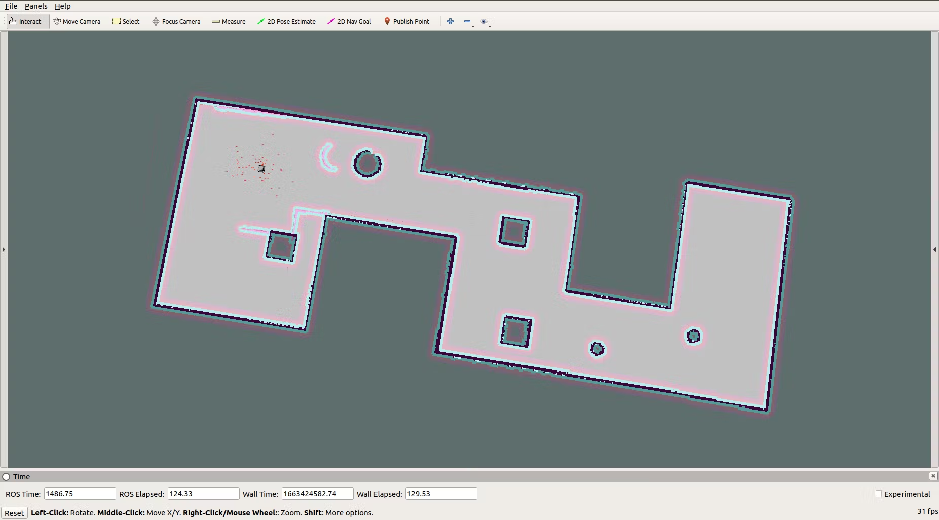
Mapping the Environment
After completing the Setup, mapping starts and can be seen on RVIZ. As the robot moves around the environment it creates a better map of the surrounding area. Once the robot has explored quite a lot of the world using teleoperation, the map is well defined and ready to be saved for further use.
-
Saving the map
Once the map is well defined, we can use the map_server package to save our map. This map can later be passed to our Navigation stack. To save the map, run the command in a new terminal after making appropriate changes.
Raw Command
rosrun map_server map_saver -f ~/catkin_ws/src/{pkg_name/location}/map_name
https://en.wikipedia.org/wiki/Simultaneous_localization_and_mapping
https://in.mathworks.com/discovery/slam.html?requestedDomain=
Autonomous Navigation means that a robot can traverse from one point to another without any human intervention. In order to do the same, a robot has to perform complex maneuvers like path planning, localization, dynamic obstacle avoidance, etc. A robot uses many sensors, algorithms, models, etc to help it achieve this amazing feat. To successfully implement Autonomous Navigation on a system, there can be many approaches. One such approach is discussed here where a Nav Stack is created using various things like AMCL, Move_Base, Map_Server, sensor, and odometry data.
http://wiki.ros.org/move_base?action=AttachFile&do=get&target=overview_tf.png
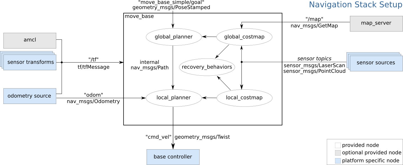
RQT graph

-
Installing the Map Server package
sudo apt-get install ros-melodic-map-server
-
Installing the AMCL package
sudo apt-get install ros-melodic-amcl
-
Installing the Move_Base package
sudo apt-get install ros-melodic-move-base

sudo apt-get install ros-melodic-dwa-local-planner
-
General Instructions
Creating a Nav Stack is the most crucial task for an Autonomous system. All the following steps have been referenced from the ROS wiki. You can refer the ROS wiki page for making these things from scratch. OR You can get these things bundled together in a file that can be downloaded for ease of access.
-
Create amcl.launch
Create a new launch file with the name amcl.launch Fill in the parameters by referring to the AMCL ROS wiki page OR Refer to the amcl.launch file inside the launch folder in the provided reference for making your own file.
-
Create a params folder
A params folder will be used to store parameter files in YAML format for various things like costmap parameters, path planner parameters, and move base. Create the following parameter files and fill in values from the ROS wiki page (or refer to the params folder provided in reference material)
local_costmap.yaml
global_costmap.yaml
dwa_planner.yaml
move_base.yaml
common_costmap.yaml
-
Create move_base.launch
Create a new launch file with the name move_base.launch Fill in the parameters by referring to the MOVE_BASE ROS wiki page OR Refer to the move_base.launch file inside the launch folder in the provided reference to make your own file. Adjust the values of location for the parameters section in the new launch file.
-
Create navigation.launch
We need a new launch file that can launch a few specific nodes and other launch files. So we will create a new launch file with the name navigation.launch Firstly, we add details to launch amcl.launch file. Next, we add details for launching the move_base.launch file. Then, we add details for launching the map_server node and supply a map file to it. Finally, we add the details to launch the Rviz node.
Refer to the navigation.launch file for reference.
-
Start the gazebo.launch file
roslaunch robot_description gazebo.launch
-
Start the navigation.launch file
roslaunch robot_description navigation.launch
-
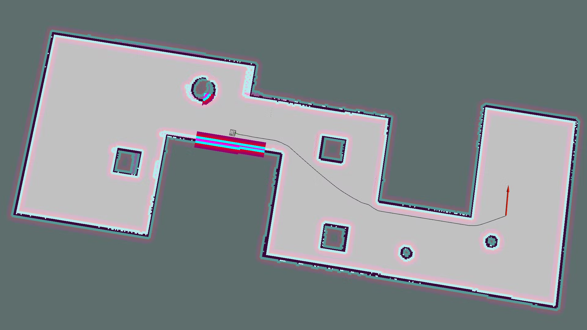
Setting up RVIZ Parameters
Goto RVIZ and click on the add section. Then click on By topic and add the following:
Laser Scan [ By topic > /scan > LaserScan ]
Map [ By topic > /map > Map ]
Global Costmap [ By topic > /move_base > /global_costmap > /costmap > Map ]
Local Costmap [ By topic > /move_base > /local_costmap > /costmap > Map ]
Polygon [ By topic > /move_base > /local_costmap > /footprint > Polygon ]
Pose Array [ By topic > /particlecloud > PoseArray ]
Pose [ By topic > /move_base > /current_goal > Pose ]
Global Path [ By topic > /move_base > /DWAPlannerROS > /global_plan > Path ]
Local Path [ By topic > /move_base > /DWAPlannerROS > /local_plan > Path ]
Final Path [ By topic > /move_base > /NavfnROS > /plan > Path ]
Finally, Click OK
-
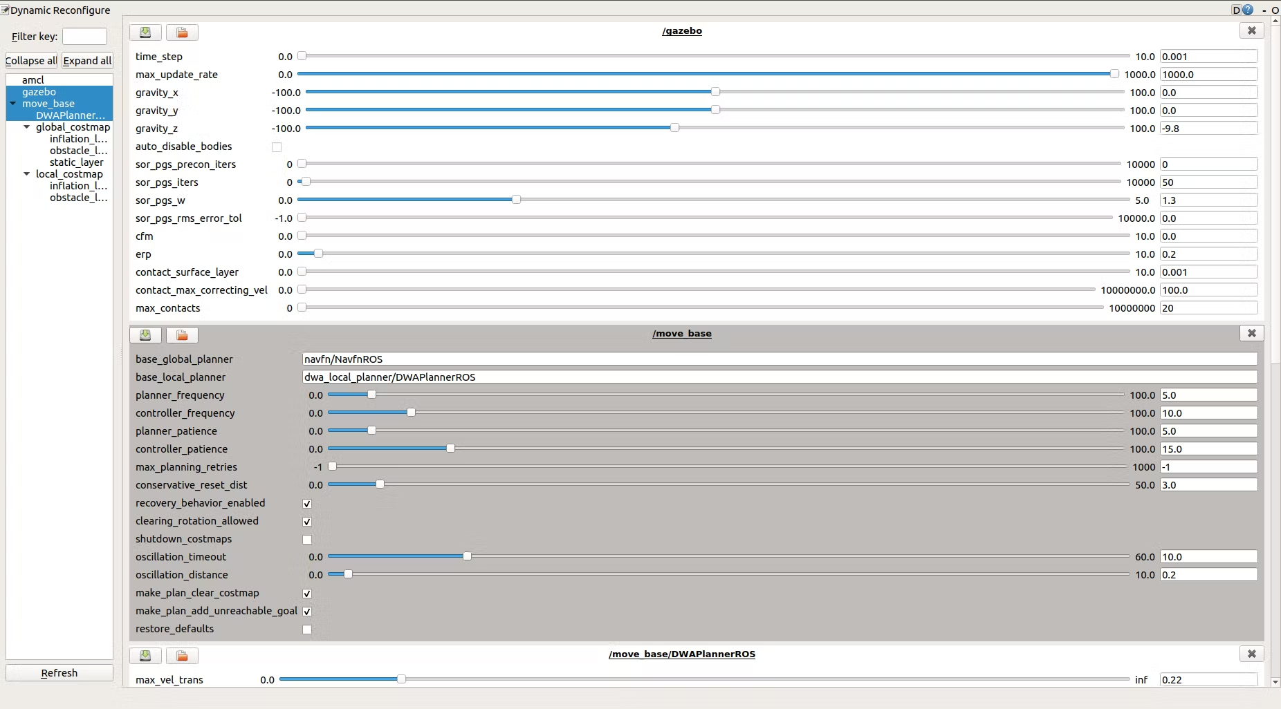
Tuning the Dynamics of Robot
Now that the robot has autonomous navigation implemented, we can further fine-tune all the parameters being provided to it to make it reach a more optimal solution. We can start with basic tuning which involves the following parameters:
- Fix your BaseFootPrint size
- Tune your Global Map parameters
- Tune your Local Map parameters
- Increase the Particle size
Once, we are done with the basic tuning, then we can shift our focus toward tuning the parameters of the DWA Planner
http://wiki.ros.org/navigation/Tutorials/RobotSetup