1.3 Basic Arduino Projects
When programming with Arduino, we use two main functions: setup() and loop(). The setup() function runs once when you power the board or press the reset button, while the loop() function runs continuously.
When creating a new sketch, here is how your code will initially look:
void setup() {
  // put your setup code here, to run once:

}

void loop() {
  // put your main code here, to run repeatedly:

}To get started, let's print some messages to the Serial Monitor. These messages are called strings, which are sequences of characters that we can display. The Arduino executes the code inside these functions, and we can see the output on our computers. When we run this on the robot, the robot will also 'see' this output.
void setup() {
  Serial.begin(9600);           // Start serial communication at 9600 bits per second
  Serial.println("Setup is starting..."); // Print message to Serial Monitor
}
In this snippet, we begin serial communication and print a message indicating that the setup has started.
void loop() {
  Serial.println("Loop is running..."); // Print message to Serial Monitor
  delay(1000);                          // Wait for a second
}
Now, in the loop() function, we print another message and introduce a delay(1000), which pauses the program for 1000 milliseconds (or 1 second).
Compile the code and Upload it at this stage, to observe what your microcontroller can do at this point.
Toggling the Onboard LED Next, we will toggle the onboard LED of the Arduino, which is usually connected to pin 13.
To control the onboard LED, we need to set the pin mode in the setup() function. Let's modify the setup:
void setup() {
  Serial.begin(9600);                  // Start serial communication
  pinMode(13, OUTPUT);                 // Set pin 13 as an OUTPUT
  Serial.println("Pin 13 set as OUTPUT.");
}Now, let's turn the LED on in the loop() function.
void loop() {
  digitalWrite(13, HIGH);              // Turn the LED on
  Serial.println("LED is ON.");        // Print status to Serial Monitor
  delay(1000);                         // Wait for a second
}Next, we will turn the LED off.
void loop() {
  digitalWrite(13, HIGH);              // Turn the LED on
  Serial.println("LED is ON.");
  delay(1000);                         // Wait for a second

  digitalWrite(13, LOW);               // Turn the LED off
  Serial.println("LED is OFF.");       // Print status to Serial Monitor
  delay(1000);                         // Wait for a second
}
Now, when you upload this code, you will see the onboard LED toggling on and off every second, and the messages will appear on the Serial Monitor.
Now let’s connect an external LED on a breadboard. You will need:
- An LED
- A 220-ohm resistor
Perform the setup as in the folloing image
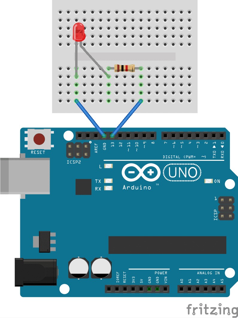
Connect the long leg (anode) of the LED to digital pin 13 on the Arduino. Connect the short leg (cathode) to one end of the resistor. Connect the other end of the resistor to the ground (GND) pin on the Arduino.
You can use the same code as before to toggle the external LED.
void setup() {
  Serial.begin(9600);
  pinMode(13, OUTPUT);
  Serial.println("Pin 13 set as OUTPUT.");
}

void loop() {
  digitalWrite(13, HIGH);
  Serial.println("LED is ON.");
  delay(1000);

  digitalWrite(13, LOW);
  Serial.println("LED is OFF.");
  delay(1000);
}