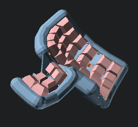
The Dactyl is a parameterized, split-hand, concave, columnar, ergonomic keyboard, originally written by Matt Adereth. See his README for general info. Here's what's different about mine:
- Round, marshmallowy sides and bottom, in contrast to adereth's minimalist squarish shape.
- (In theory) more configurability, like for different numbers of rows and columns. The thumb is still kind of hardcoded, and there are still hacks.
The keyboard is written as a Clojure program, which emits OpenSCAD code, and as some lower-level OpenSCAD code. Unlike in the original repository, I don't tend to keep the .scad and .stl files emitted by the program in the repository and downloadable. Maybe once I get to 1.0.
- Install the Clojure runtime
- Install the Leiningen project manager
- Install OpenSCAD
- Clone https://github.com/adereth/unicode-math;
lein installit so you have version 0.2.1 ready.
- Run
lein repl - Load the file
(load-file "src/dactyl_keyboard/dactyl.clj") - This will generate the
things/*.scadfiles - In the
thingsdirectory,make -k -j8(it is a GNU makefile). This will build the.stlfiles - and take a half an hour, likely.
- Have an
.scadfile open in OpenSCAD. - Have this command running:
sh editloop.sh --no-fstl src/dactyl_keyboard/dactyl.clj dactyl-blank-all - Make changes to the design, save files, watch as everything is rerun.
There are faster things you can do (keep the REPL open, and do the
(load-file) again), and nicer things (CIDER), but this way works for
me and I left it at that.
You can change the definitions of skip-tags and emit-tags in
dactyl.clj to avoid creating some outputs. This can save time if you
are iterating on a part and not the whole keyboard. The keywords you
can put in are just below, in make-filename. For example, to avoid
emitting the left half, change the definition of skip-tags to:
(def skip-tags #{:left})
Filename convention:
[object]-[lr]-[part][piece].stl

e.g.
dm-l-bot01.stl
dm stands for Dactyl Marshmallow. lr is l for the left hand, r
for the right. Parts are bot for bottom, sid for sides, fra for
frame, and screw-hole-top. File names are short so you can tell them
apart on a small LCD display such as you may have on your 3D
printer. There may not be .stl files for every numbered piece of the
bot part; this is ok. Print one of each piece, and ten
screw-hole-tops. (Don't print debug-* files.) Print also a
teensy-holder-a and a teensy-holder-b.
Put your controller into the holder, put the two holder pieces together, and contrive to hold them that way, likely by gluing, but maybe temporarily with a rubber band. You may not want to stick the controller in permanently until after you've soldered the wires onto it.
Numbered pieces of each dm part should be glued together. To glue
the bottom, tie pieces together with fishing line, and hold tight
while applying Sci-Grip 4 (acrylic weld, with dichloromethane, danger,
read safety directions) or liquid cyanoacrylate. To glue the frame,
use spring clamps while applying very thin glue such as the foregoing.
Press threaded inserts into the ten screw hole tops using a soldering
iron. Then glue them onto the waffly bits on top of the bot
part. Glue the legs on the bottom.
Press a threaded insert into the screw hole in the bottom of one of
the frame pieces. This is where the teensy-holder screws in.
Install the connectors into the sides pieces. The USB extension just screws on; the RJ-11... who knows. Glue?
Once you've installed keyswitches into the frame, done your wiring, and soldered the wires to the controller, you can screw the frame to the bottom. Then maybe it's a good time to glue the sides on. Figure out how you are going to get the last piece in place with all the other ones already glued, before you start gluing.
This is how I imagine it all goes together. I've still never gotten all the pieces printed yet! I keep making little changes.
Copyright © 2015, 2018 Matthew Adereth and Jared Jennings
The source code for generating the models (everything excluding the things/ and resources/ directories is distributed under the GNU AFFERO GENERAL PUBLIC LICENSE Version 3. The generated models and PCB designs are distributed under the Creative Commons Attribution-ShareAlike License Version 4.0.