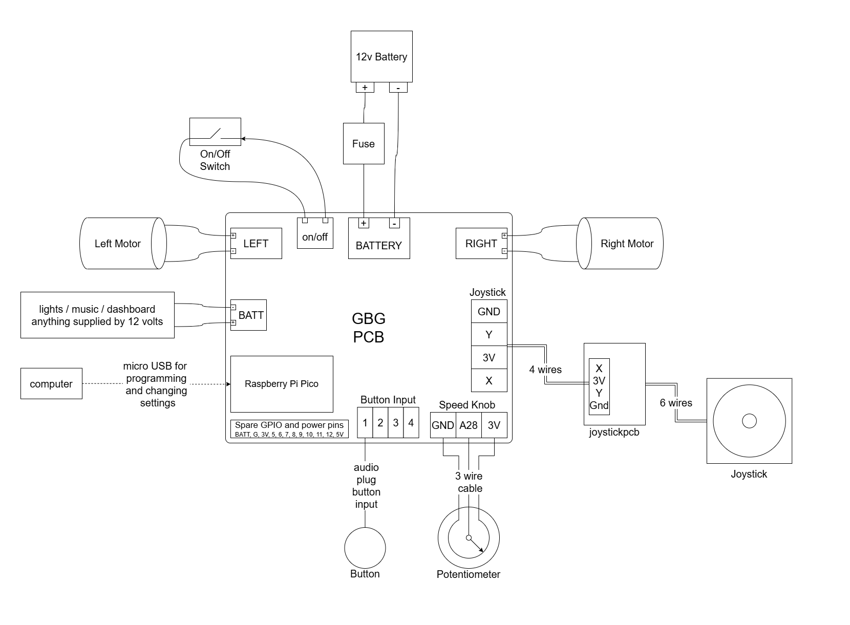
A PCB for controlling the motors in a go baby go car with joystick control
https://github.com/gobabygocarswithjoysticks/gbg-pcb
![]()
questions? post here or email gobabygocarswithjoysticks@gmail.com
Use KiCAD 9.0
Run this github action when you push changes to any of the KiCAD files. The action updates the images of the CAD, the gerber files, the schematic, and other PCB production files.
 //TODO: NEW PHOTOS


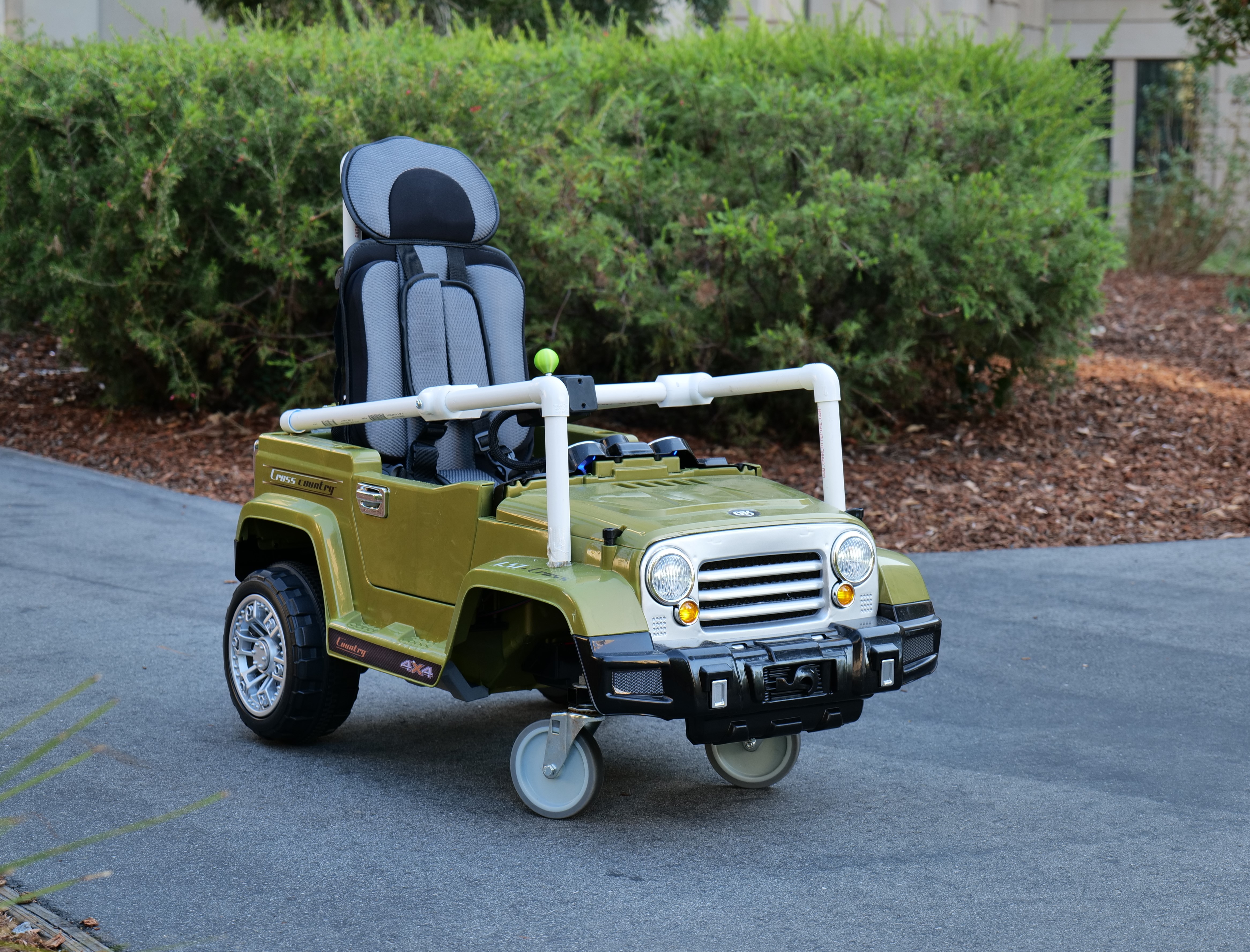
I put 20 pounds in the car, then drove it on grass and up hills. The car handled better on grass when it had weight in it. On grass, the car wasn't always able to spin in place without the wheels just slipping, but with a little forward movement it could make sharp turns.
I drove the car on a flat street with no extra weight, and the car drove for a mile (1.6 km) and still had charge left.
The motors and wires in the car got hotter than the PCB, so I think that the PCB can handle enough current for this model of car.
I put approximately 70 pounds in the car and drove it into a wall so the wheels slid but heavily loaded the motors. The thermal breaker in the car tripped after a couple minutes before the PCB had gotten hot at all, but the motors and wiring of the car was hot.

That is practically zero current. The PCB won't make the battery discharge any faster than the battery would just sitting in storage with nothing connected.
I measured the current by adding a 3MOhm resistor in series with the PCB and a 12V power supply. I measured the voltage across the resistor as 5.5mV and then calculated the current that was flowing through the resistor and PCB.
I=V/R=0.0055/3000000=1.83E-9 Amps
I used a CIM motor that was prevented from turning as the load. I adjusted the duty cycle of the motor drivers with the joystick. I used a ACS758LCB-050U-PFF-T current sensor.
For 2 minutes I used the joystick to keep the reading from the current sensor at approximately 10 Amps. The temperature of the motor drivers stabilized at around 100 degrees C.
The board was able to supply 40 amps to one motor for about 3 seconds before the over temperature protection of the motor drivers activated.
If a motor starts turning on and off about once per second when under a lot of load, that is the over temperature protection of the motor drivers (150 degrees C). Try to avoid this by moving the car to a smoother surface to reduce the load on the motors. It's not good for the drivers to overload them repeatedly.

It won't run on 6 volts. The motor driver ICs need over 8 volts.
It hasn't been tested above 12 Volts.
The PCB was only designed for 12 Volt ride on cars. Feel free to email if you are interested in trying it at other voltages.
The motor driver chips specify 8-40 volts P_4.2.1
The voltage regulator for the Pico is rated for 9-18 volts D78B05T-1.0
Some of the resistors would overheat at 24 volts.
The reverse voltage protection MOSFETS need to be redesigned. The motor drivers work and the circuit board supplied 15A (at 100% duty cycle) from one motor port for 4 minutes without overheating. The motor driver was running at 100% so there was no heat generated from switching.
Thank you to PCBWay for supporting this project. I appreciate the high quality boards and great service.