Electronic_AGT


An AGT is a converter to adapt a historic teletype with current loop (TW39) to an austrian frequency shift keying station (V.21).
The device contains of
- Two galvanic isolated regulated power supplies sourced by one transformer
- -60V, LGND and +60V for current loop (TW39)
- DGND and +12V for SES-B-card and logic
- converter electronic H-bridge (RX, TX) for current loop
- connector slot for a SES-B-card (V.21 transceiver)
- ADo8 female connector for teletype current loop
- ADo8 male cable to station (V.21)
- power connector (Shuko) for teletype power
- power cable (Shuko) to wall outlet
- housing
- (much place for hacks)
The name stands for German "Anschaltgerät"
IMPORTANT! A SEU-B-card (ED1000) does not work in this AGT because of missing -12V supply (-B, pin 18)


The AGT is available for low money but it is not delivered with the SES-B-card.
The idea was to use:
- the power supply with +60V and -60V (=120V) for the current loop (TW39)
- the 12V for powering the micro-controller (uC) - or better the 20V before the linear regulator (additional cable needed)
- the H-bridge for pulsing data and switching polarity of the current loop
- the ADo8 connector to plugin the teletype with original (historical) connectors
- the power connector (Shuko) and a SSR to switch power of the teletype (optional)
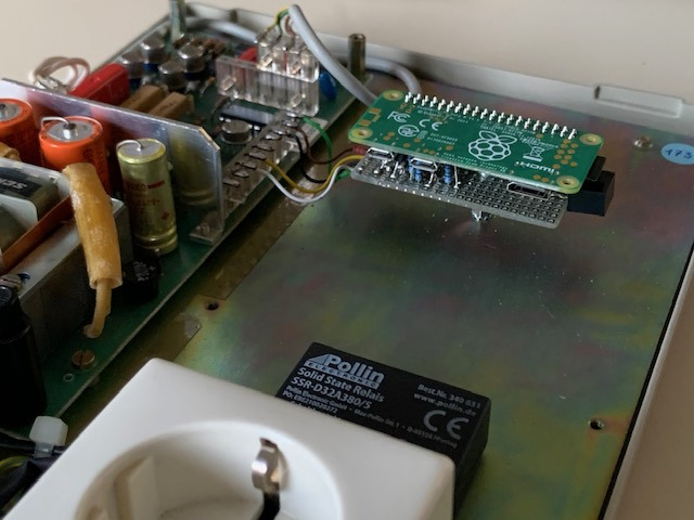
To adapt a uC (e.g. ESP32, Raspberry Pi) to the AGT only 3 transistors, a z-diode and 4 resistors are needed. Alternatively an ULN2003 can be used.
To power the uC a DC/DC converter to 5V is needed.

Note: For simpler adaptions the TXD and/or RXD have to be inverted in software or in voltage converter (transistors)
Status: tested and working
There are 2 independent supplys on the same PCB.
The +60V and -60V part has a common ground. Over the H-bridge the supply provides the 120V for the current loop. The voltage is regulated by darlington transistors and z-diodes.
The 12V part powers the data side (TX, RX) and the SES-B device. The voltage is regulated by a LM7812 regulator.
For powering a bigger uC (like RPi) it is recommended to use the voltage before the regulator (20V) to prevent overheating the LM7812.
Note: The 60V and 12V parts are galvanic isolated.
IMPORTANT! The 0V-power-level is connected to earth (PE). Using an oscilloscope can damage the circuit!
| Pin | Cable Color | Name | Comment |
|---|---|---|---|
| 1 | wt | in b | connected to X2-1 and ADo8-cable pin 4 and SES-B-card pin 3 |
| 2 | br | in a | connected to X2-2 and ADo8-cable pin 1 and SES-B-card pin 2 |
| 3 | gn | out b | connected to ADo8 pin 4 |
| 4 | ye | out a | connected to ADo8 pin 1 |
| 5 | nc | ||
| 6 | 12V | 12V | |
| 7 | DGND | DGND |
| Pin | Cable Color | SEU-B Pin | SEU-B Name | Comment |
|---|---|---|---|---|
| 1 | wt | 3 | b | connected to X1-1 |
| 2 | br | 2 | a | connected to X1-2 |
| 3 | gn | 4 | T0 | DGND |
| 4 | ye | 9 | +T | 12V |
| 5 | gy | 11 | -T | DGND |
| 6 | rs | 12 | Dan | RX - from AGT to uC |
| 7 | bl | 15 | Dab | TX - from uC to AGT |
| 8 | rd | 17 | +B | 12V |
| 9 | bk | 19 | B0 | DGND |
With the TX pin a micro-controller can transmit serial data to the current loop as well switching the polarity.
With a continuos level of 12V (TX pin is open - pullup resistor with 5.6kOhm lifts to 12V) the polarity of the current loop is in data transmitting state (negative current).
Pulsing (shortening and opening a switch to GND) the TX pin transmits data to the current loop with a 12V=40mA loop and 0V=open loop.
With a continuos level of 0V (TX pin is shorted to GND) the polarity of the current loop is reversed to signal the offline state (positive current). After pulsing a level of 0V for more than 0.5...1 sec switches to this mode.

Diagram - Data FLow TX: 2sec 0V - 3sec 12V - 3sec Pulsing - 3sec 0V
| Pin | ADo8 Pin | 12V (Pullup) | Pulsing | 0V (connected to GND) |
|---|---|---|---|---|
| State | Active, no Data | Transmitting Data | Offline | |
| X2-3 | 4 | +60V | +60V / 0V | -60V |
| X2-4 | 1 | -60V | -60V / 0V | +60V |
The TX-pin uses a pullup resistor of 5.6kOhm. Use a NPN transistor to GND for transmitting data and change state.
The RX has a in line resistor of 2.2kOhm
| Closed Loop (40mA) | Open Loop |
|---|---|
| 12V | 0V |
If a connector is plugged in into ADo8, the RX signal is hold to 12V if TX is pulsing. If connector is not plugged in, the RX follows the TX signal.
