Software side of our Instruments and Prototyping Lab home security system prototype. Gave handy experience and practice with regards to embedded programming, PCB design, soldering, and using common electronics lab instrumentation to test and debug systems.
Implemented with a Texas Instruments MSP430FR4133 MCU. Decided to use four reed switches to represent "different zones" in a "household". Detection of anything magnetic closes the local circuit and sends an output signal accordingly to our audio transduscer (our alarm system). Statuses of each zone are displayed on the MCU LCD display - specific characters represent whether a zone is in danger, unarmed, or currently 'watching'/'monitoring'. Additionally, used LEDs on our custom manufactured PCB to represent zone status as well (different colour for a different state). One zone was set up to also detect sound - if the detected sound through the Analog-to-Digital converter was above a certain threshold, this would also trigger the alarm.
Used tight-polling to continually monitor our zones, interrupts to interact with components such as our sound sensor / mic.
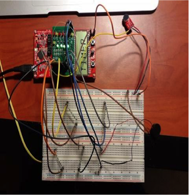
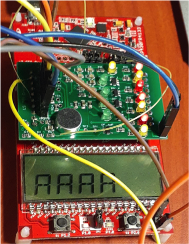
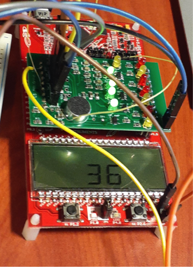
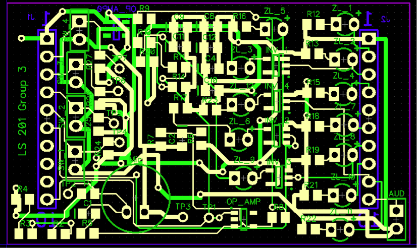
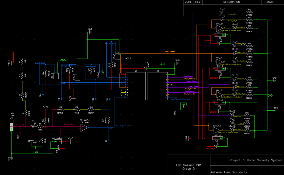
Used Diptrace to create these design schematics. Actually ran into problems with our design that needed to be fixed via. directly cutting traces on the board and using flywires to correct our connections - incorrectly mapped our sound detection component to a non-analog pin, as an example. Can see in above photos that there are some thin wires that stretch over and around the top of the board, those are our flywires for impromptu fixes. The below pictures are our original schematics, pre-fix.