Build Guide (In Progress)
NOTE: All T Nuts should be pre-assembly unless stated.
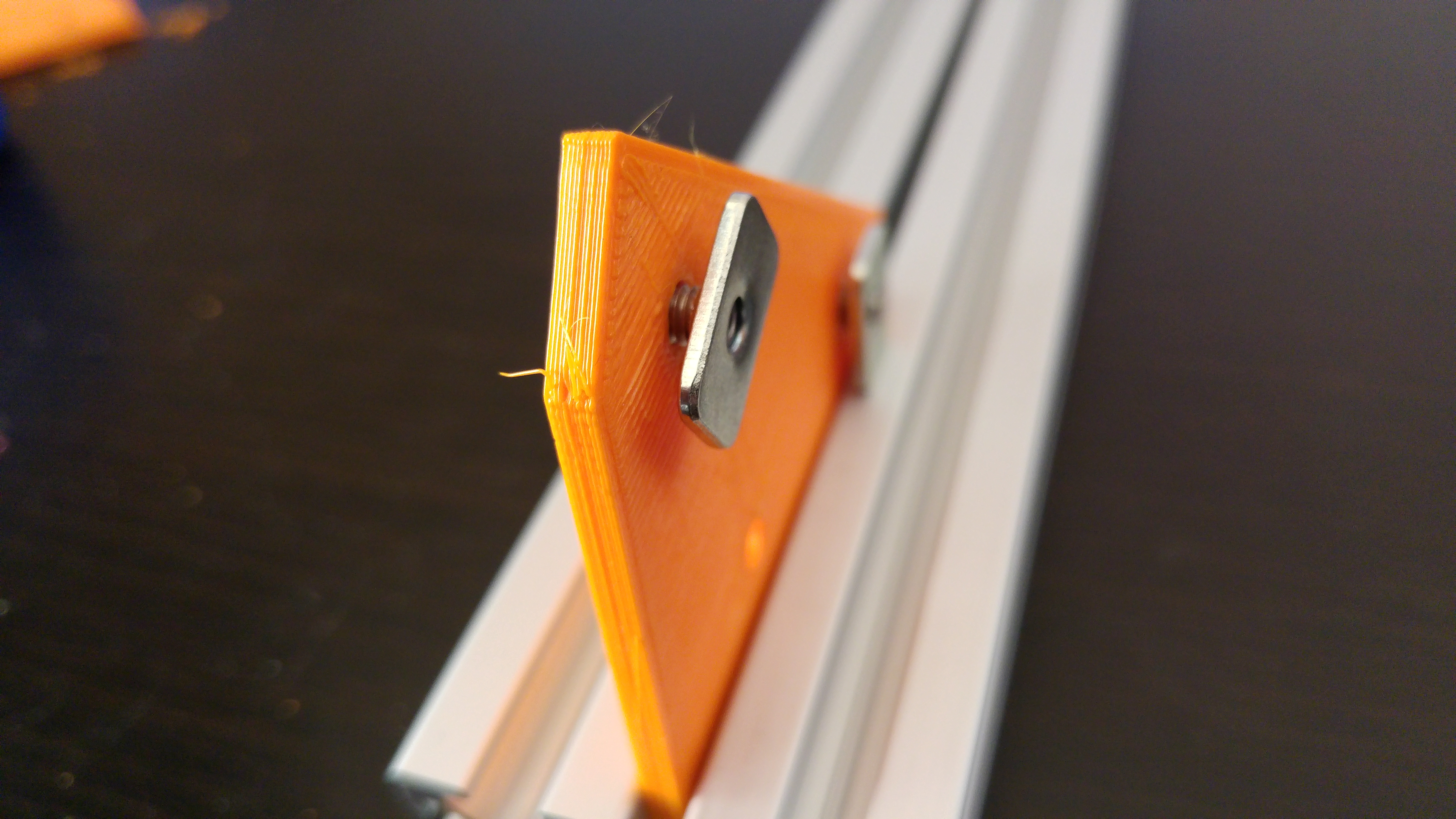
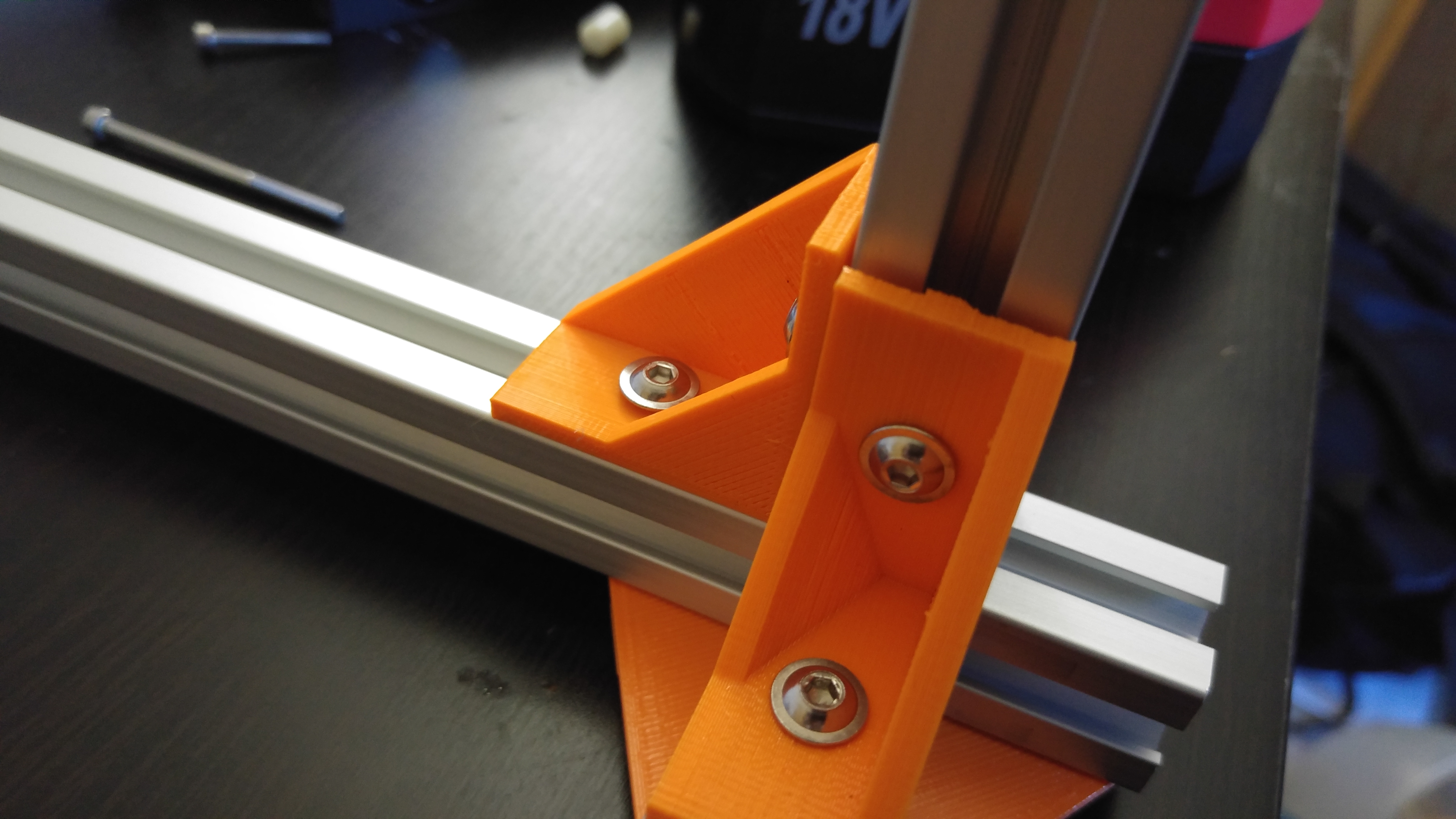
Pre-Assembly T Nuts are just that, they need to be added to the part before assembly like so:
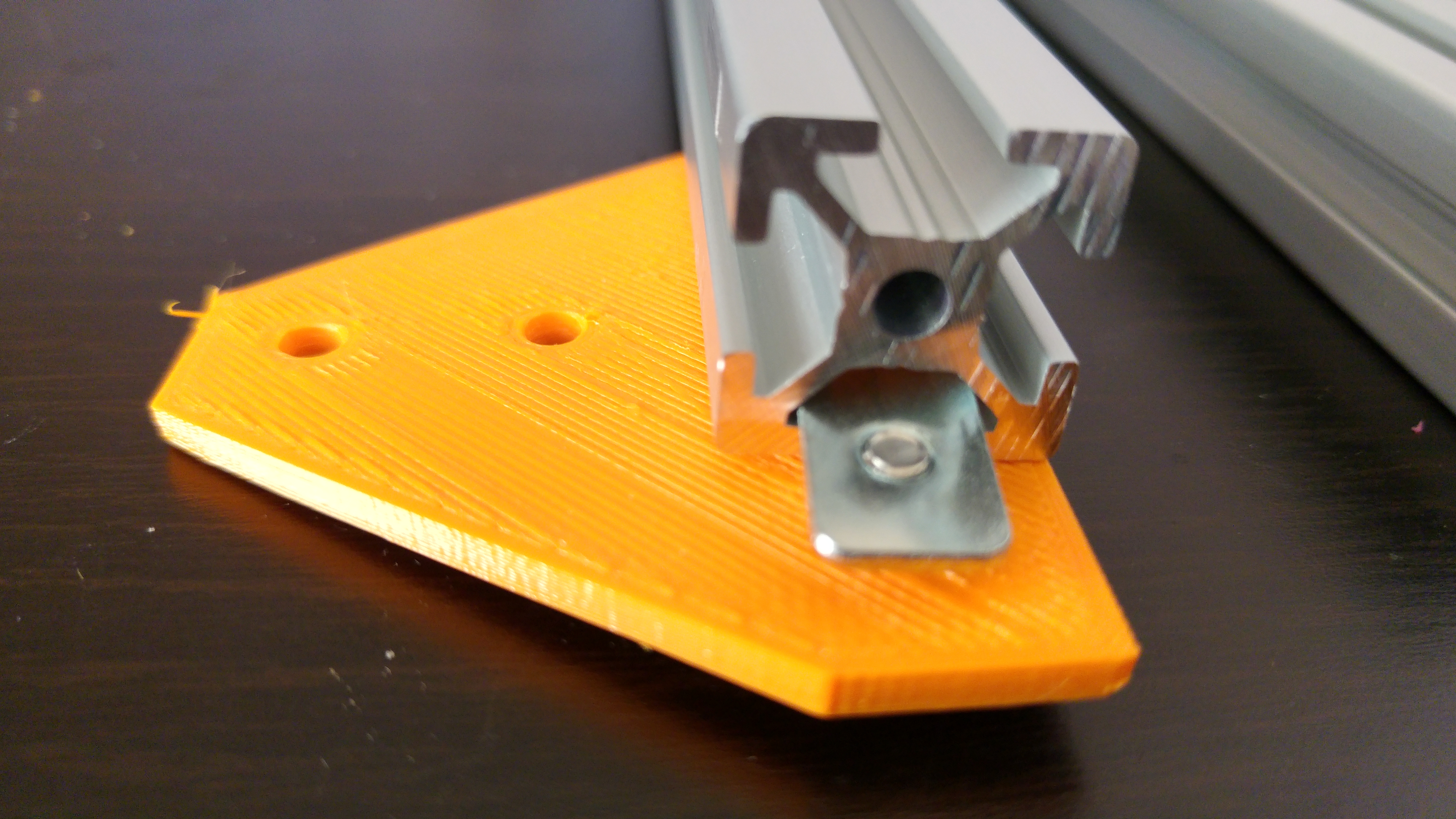
The part can then be slid into the extrusion and tightened:
All structural parts require the pre-assembly type of T Nut and 8mm M4 Bolts.
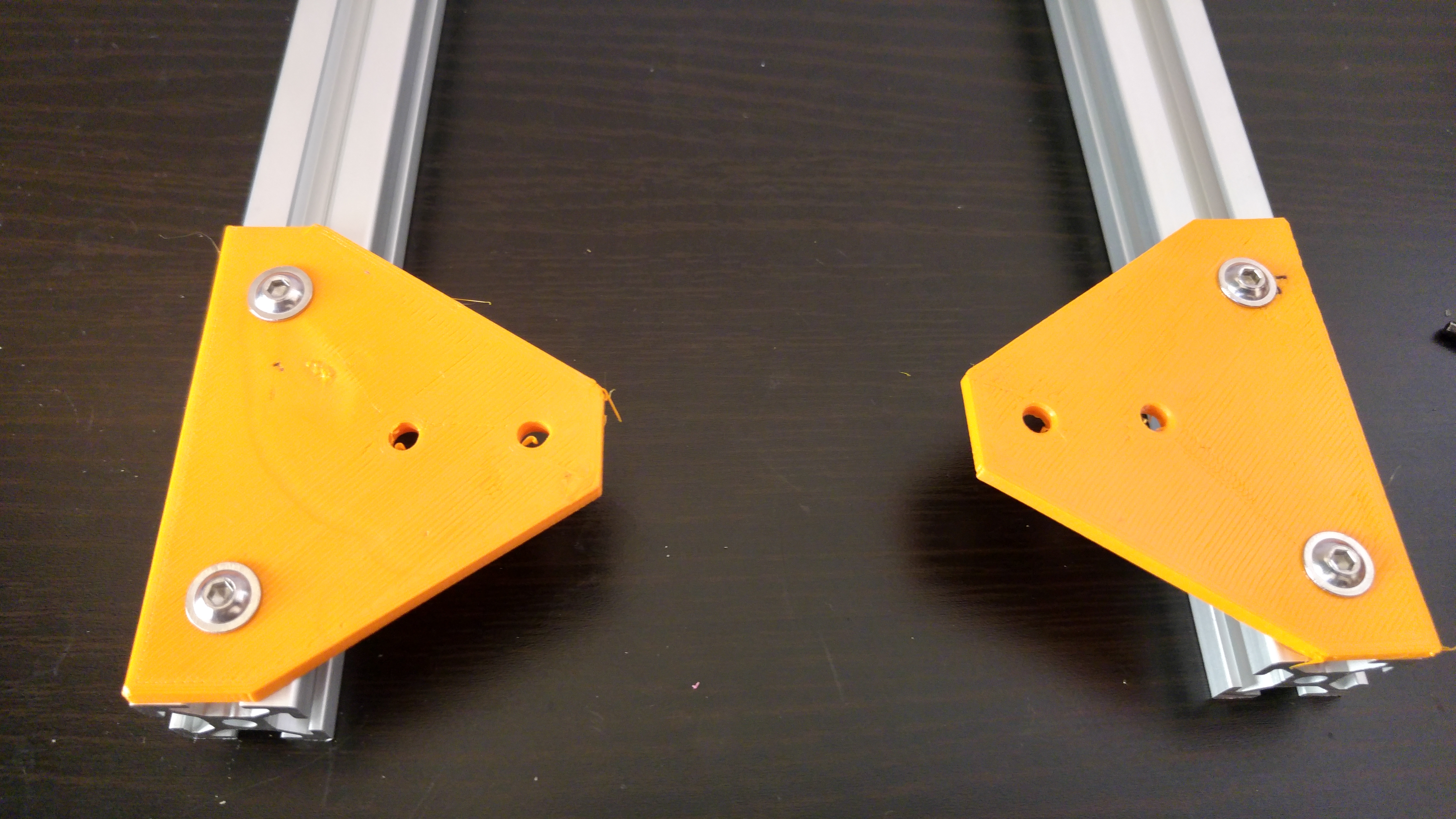
Take the 2 of the 345mm (FB2020 Standard) or 2 of the 445mm (FB2020 +) extrusions and slide the 2 of 4 bottom corner brackets in and tighten, one per extrusion so they mirror each other:
Next, take a 380mm extrusion and then place 2 corner brackets at each end, once again, mirroring each other. Slide one end of the 380mm extrusion into the bottom corner bracket with the corner bracket on the opposite side, making sure the extrusion butts up against the vertical one tightly, tighten the bolts:
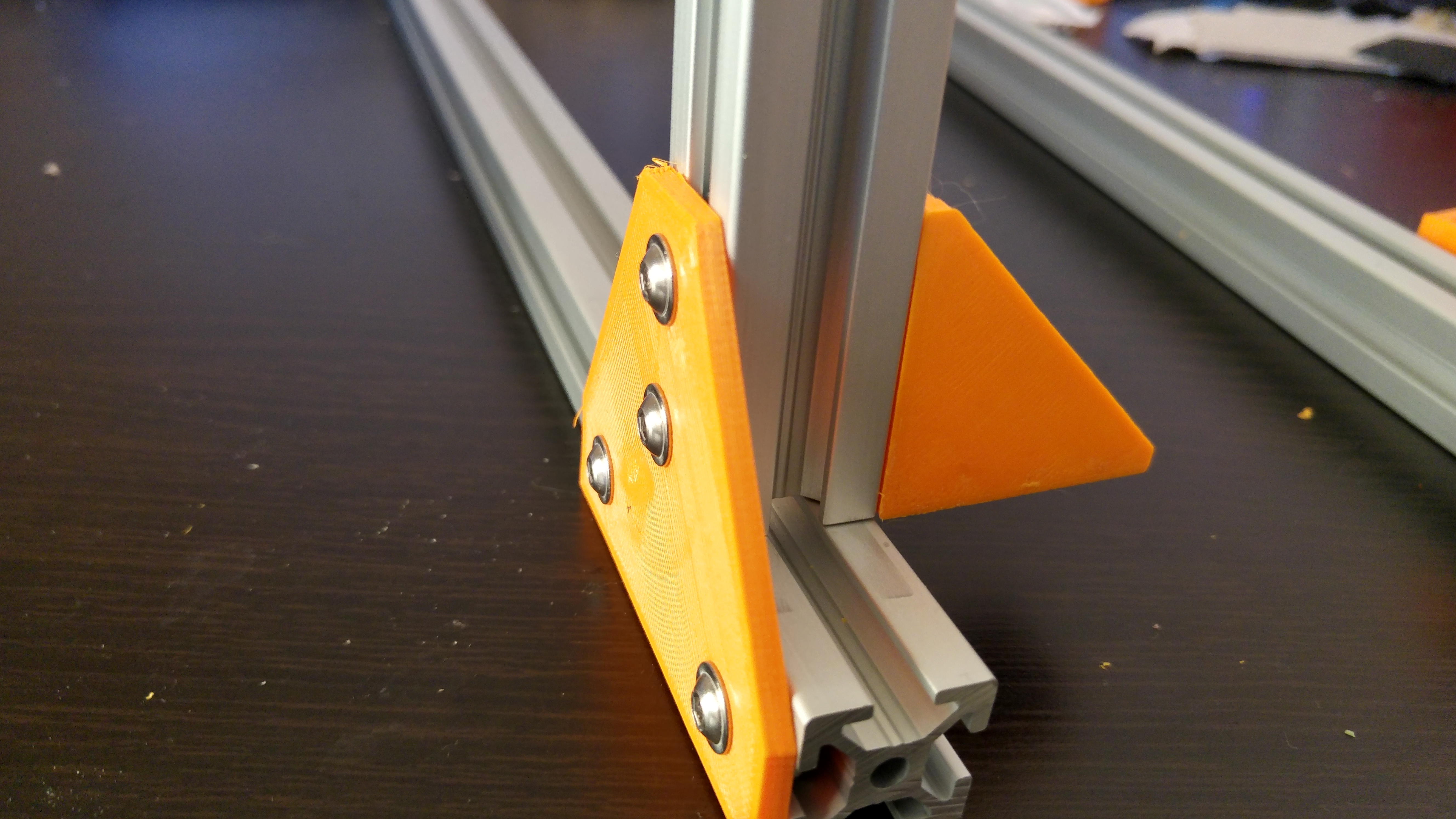
Repeat this for the opposite end. You should now have a U shape.
Now take another 380mm extrusion and insert 2 corner brackets, once again mirroring each other with the opposite face of the bracket facing so it can slide into the top of the U shape. Next take the left and right idlers and slide them into the extrusion so they are facing away from the side the Bottom corner brackets face.
Do Not insert the bearings at this point as it will make it difficult to insert the T Nuts for the Y Axis Extrusions
Slide the corner brackets into the U shape frame so the bottom of the inserted extrusion is level with the top of the vertical ones.
As with the front of the frame prepare 2 of the 345mm (FB2020 Standard) or 2 of the 445mm (FB2020 +) extrusions with bottom corner brackets.
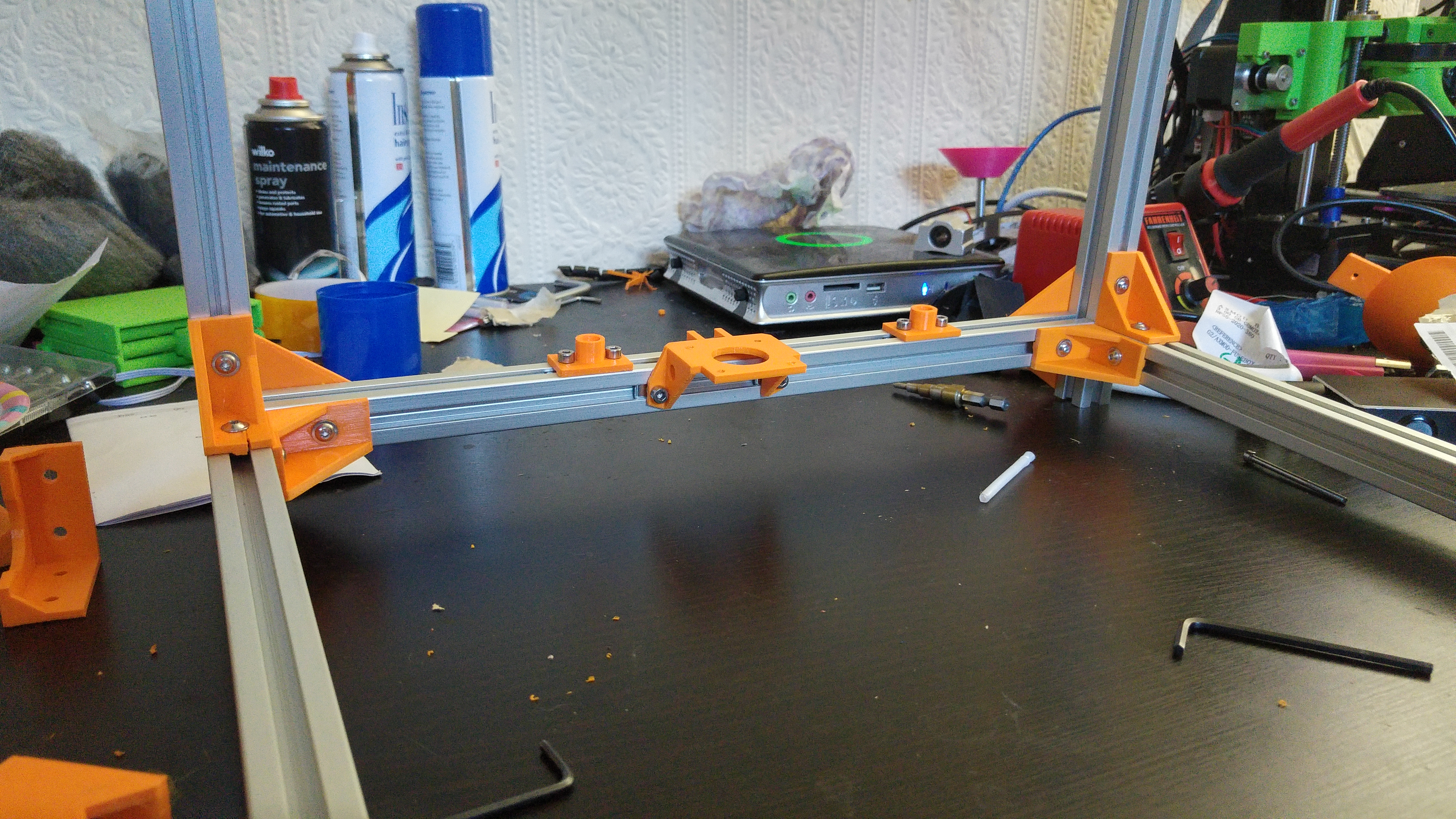
Now, take a 380mm extrusion and add the following parts: 2 Corner Brackets, 2 of the Z Rod Holders and the Z motor mount. Arrange them as shown in the following image:
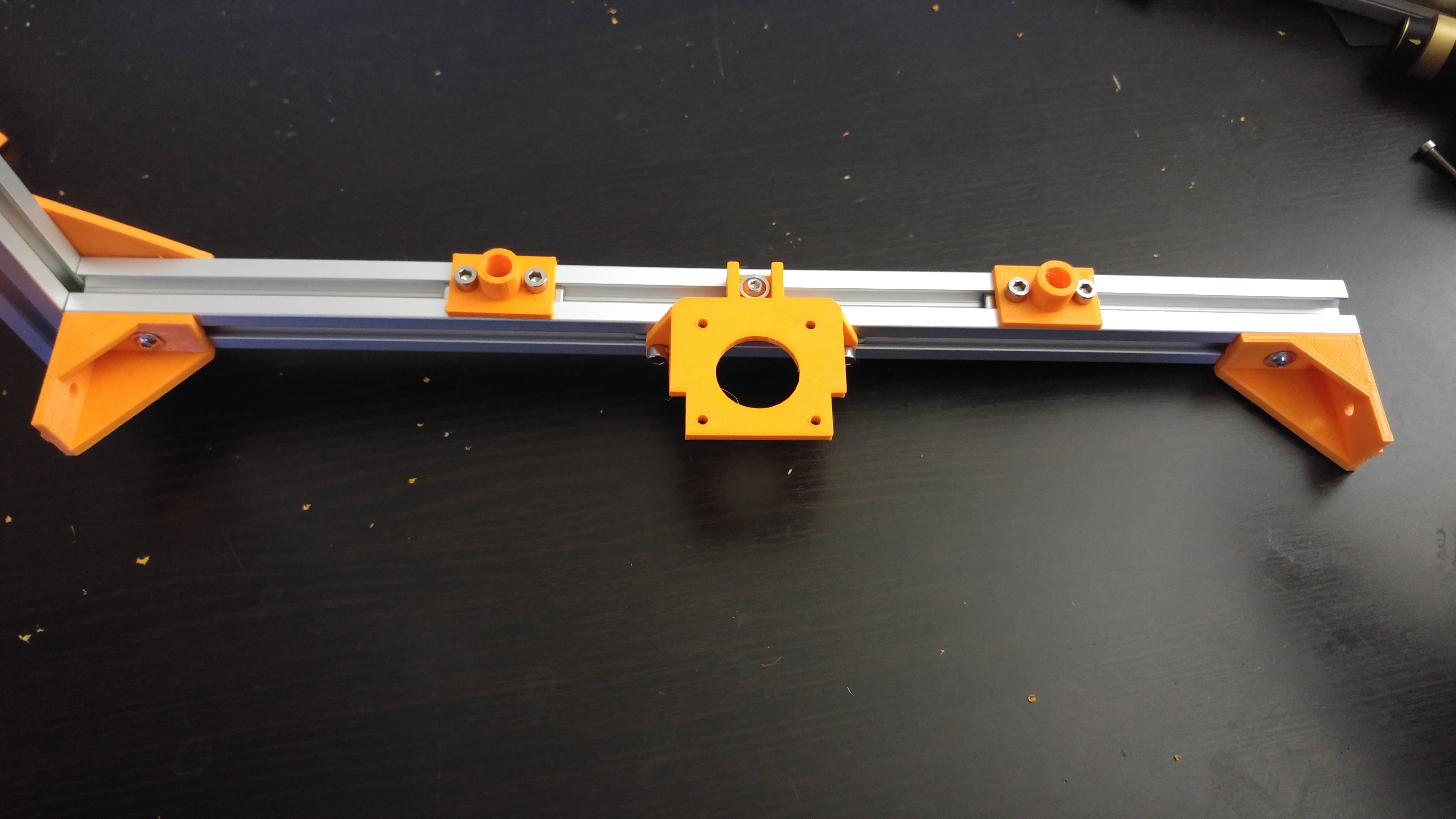
Next, as with the front take the remaining 2 of the 345mm (FB2020 Standard) or 2 of the 445mm (FB2020 +) extrusions and slide the remaining 2 of 4 bottom corner brackets in and tighten. Connect this as at either end as shown in the above image.
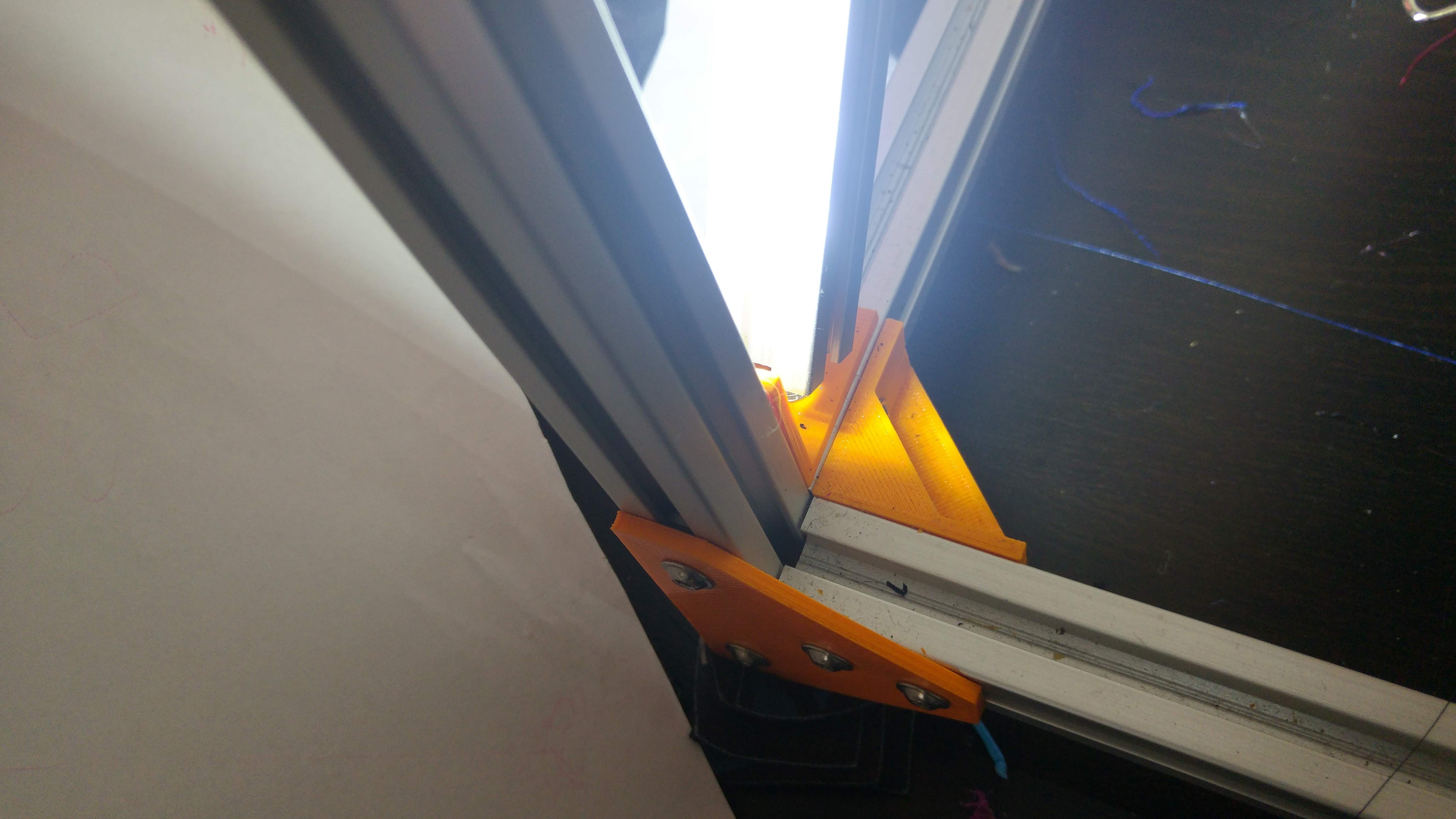
On the front vertical extrusions, insert 2 Corner Brace Brackets on either side, then insert the 2 300mm Extrusions so they butt up snugly with the front U shape.
At this point you can either install the PSU brackets on the right hand side using printed T Nuts or use Drop in T-Nuts and install it later.
On the rear U shape install 2 corner brackets on the uprights and connect to the front assembly, making sure they butt up snugly to the uprights. The front and back should now be joined together.
Take the left and right Z carriers and install the T Nuts into all 4mm holes.
Take the 2 235mm Extrusions and insert and tighten them so they will be pointing along what will be the Y Axis. Next, with one of the 147mm extrusions insert the Z nut holder with the flat face facing upwards, this is important, you will lose Z height if the Nut holder is installed incorrectly.
Connect the Z carriers making sure the Nut holder is facing away from the build area.
With the final 147mm extrusion install the left and right bed tie brackets with the two holes so they will connect to the Y axis extrusions and on the opposite side, install the 3 point bed bracket.
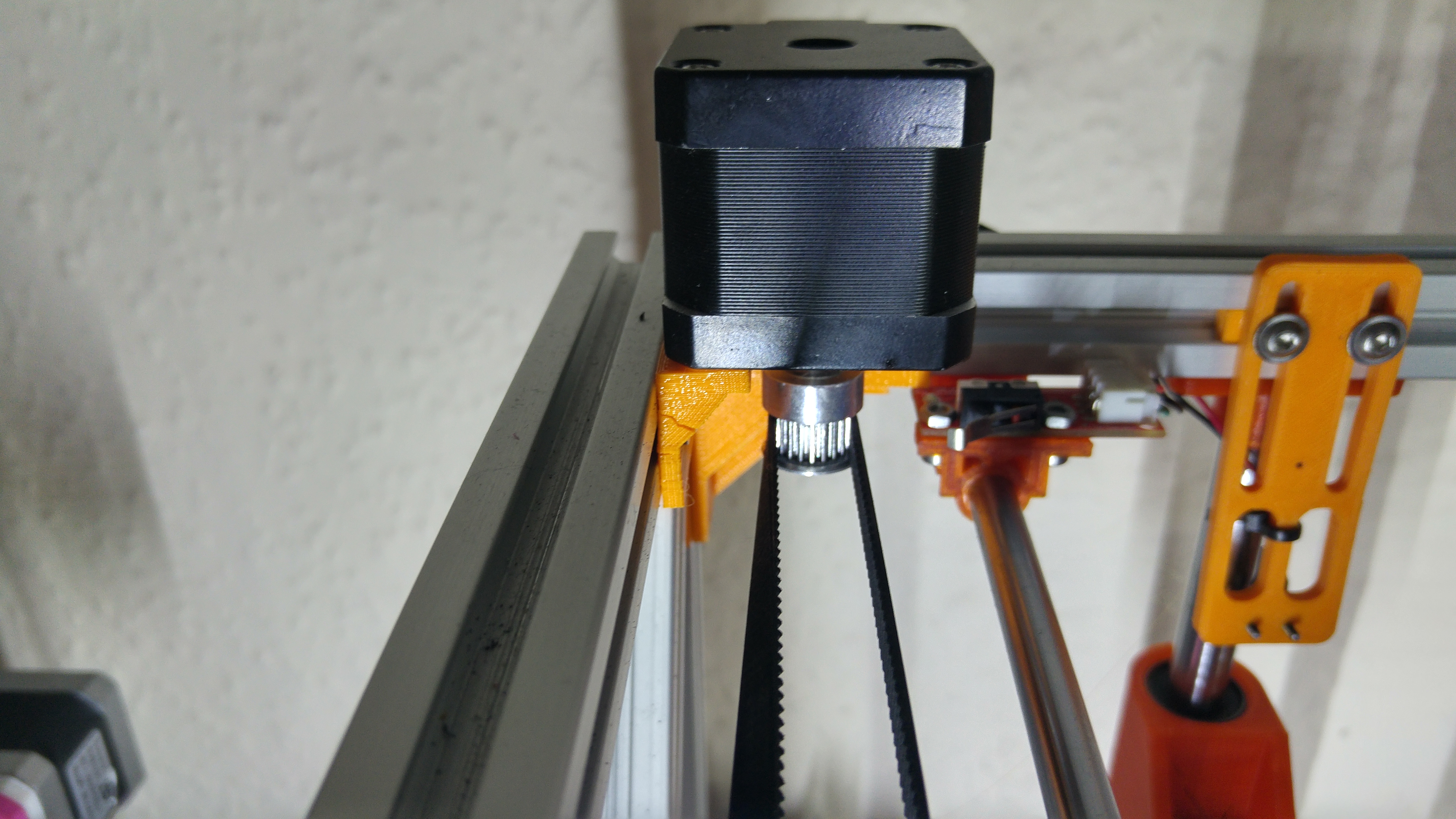
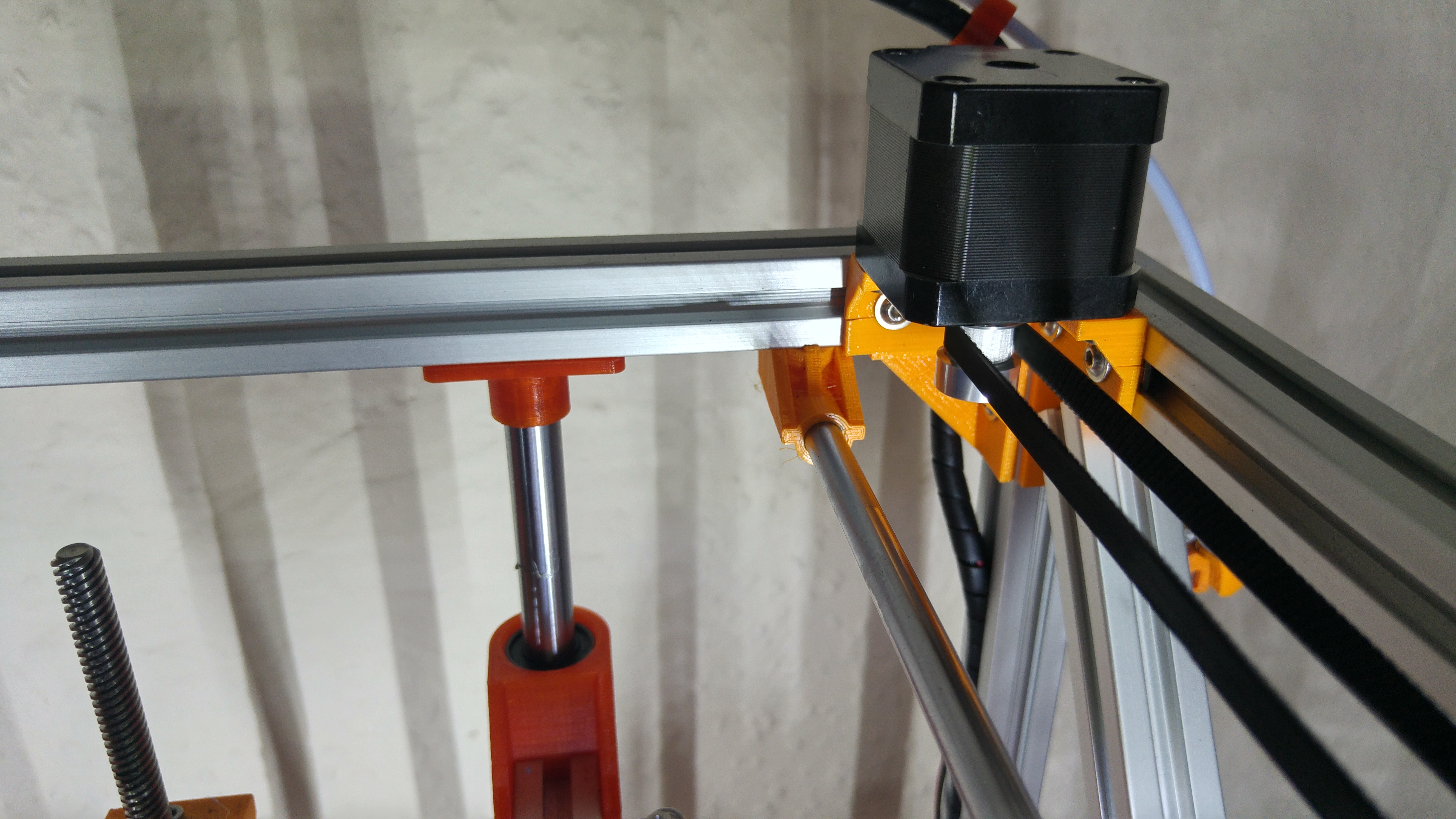
Take the 2 12mm diameter Smooth rods and install them into the holders on the lower back extrusion. Next slide the bed assembly over the rods and cap them with the final 2 Z Rod holders. Make sure the Z Rods are flush on both ends. Next take 2 Corner Brackets and install them at the top of the U shape then slide the final 300mm extrusion into place making sure to catch all the T Nuts. This should mirror the front 300mm extrusion in that the bottom of the extrusion should be flush with the top of the vertical ones. Next take your motor brackets and install your motors, making sure the wiring faces to the rear. You can install the pulleys now or later. The Left motor should have the pulley with the thin side facing downward, flush with the end of the spindle, the right should be the opposite with roughly 1mm of spindle showing at the bottom.
On the top of the back vertical extrusion install the final 2 corner brace brackets, on the top of the front vertical install the final corner brackets. Slide the 2 340mm extrusions into place making sure the ends are flush with the outside edges of the vertical extrusions.
In the corner brace bracket tabs install 4 drop in T Nuts. Take the last 2 380mm (FB2020) or the 2 465mm (FB2020 +) Line the drop in T Nuts up with the extrusion groove and tighten slowly, making sure the T Nuts lock into place.
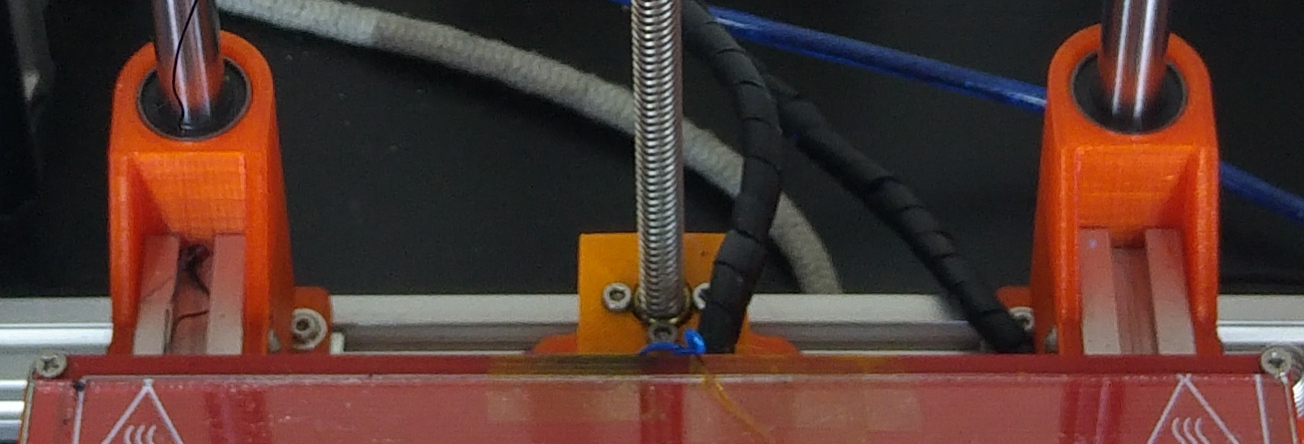
Install the motor to the Z Motor mount with the wires facing toward the right. Drop in the lead screw from the top through the nut and tighten into the coupler.
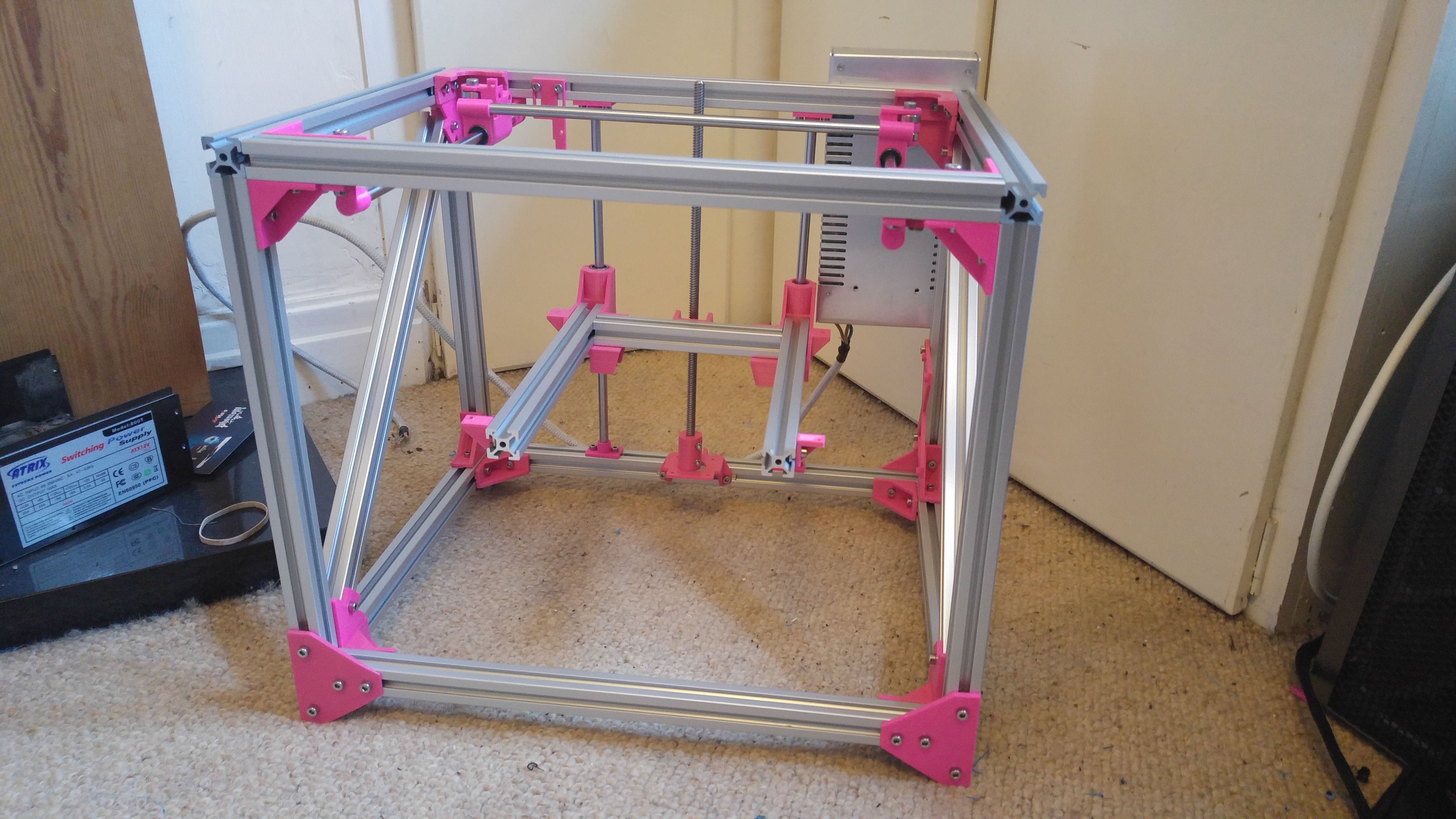
The frame should now be fully assembled. Make sure it is square by measuring all diagonals, they should all be equal.
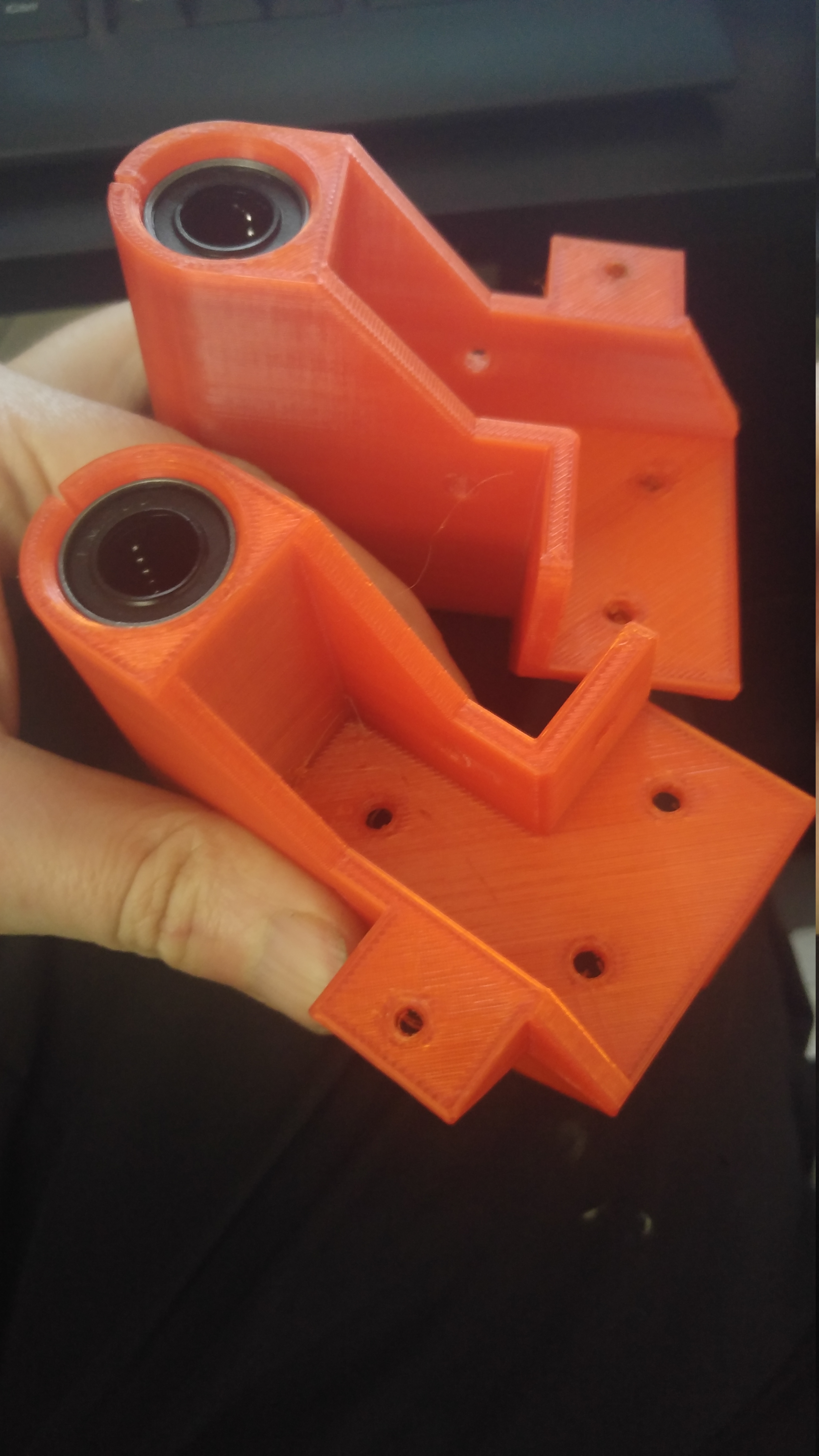
Take 2 of the 300mm Smooth rods and slide them into the bearings on the Extruder carriage, making sure that the endstop switch is pointing to the left. Next take the Y Carriages and push them on to the ends of the rods, the left hand side one should have a protruding notch to catch the endstop. Do not push them all the way as this will not leave enough travel for the X Axis.
Take 1 300mm Smooth Rod and install one of the 2 plain rod carriers on one end. Push the rod through the left hand side and install the Endstop Rod Carrier on the other end. On the rod carriers install 2 drop in T Nuts. Mount this to the underside of the top of the frame. This may be easier by putting the printer on it's side as it can be fiddly to get the drop in T nuts to turn and lock when the printer is the correct way up. Take the final 300mm Smooth rod and on one end install the right idler rod carrier, slide the rod through the right Y carrier and cap with the final rod carrier. Install 2 drop in T Nuts and tighten to the frame.
Make sure the Y axis rods are as close as you can get to each of the motor holders or idlers. Make sure the Y axis rods are parallel and central by measuring the the distance to the rods from the frame. The Carriage should slide freely on both X & Y Axes.
Take the 625zz Bearings and install into the front idlers using 16mm long M5 Bolts and the Y Carriages using 25mm M5 Bolts.
Core XY uses 2 belts and are installed as per the diagram below, Blue being the top belt and red being the bottom.
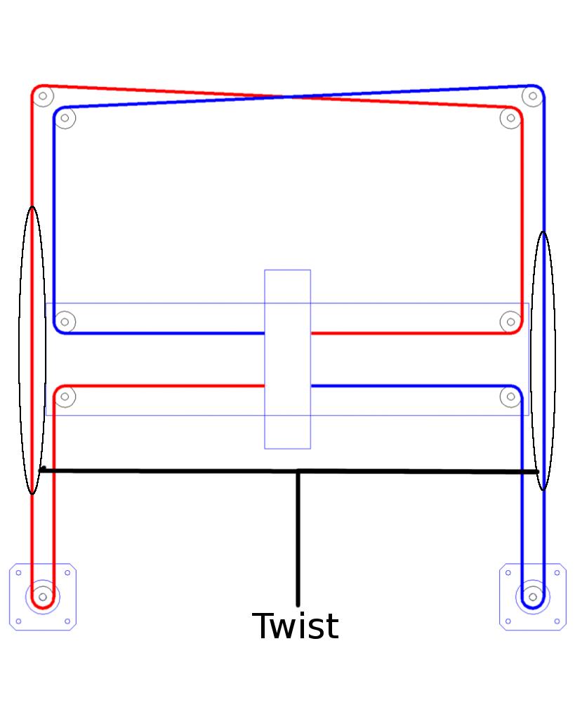
The outside run must have a twist in so the flat side of the belt runs against the idler bearings.
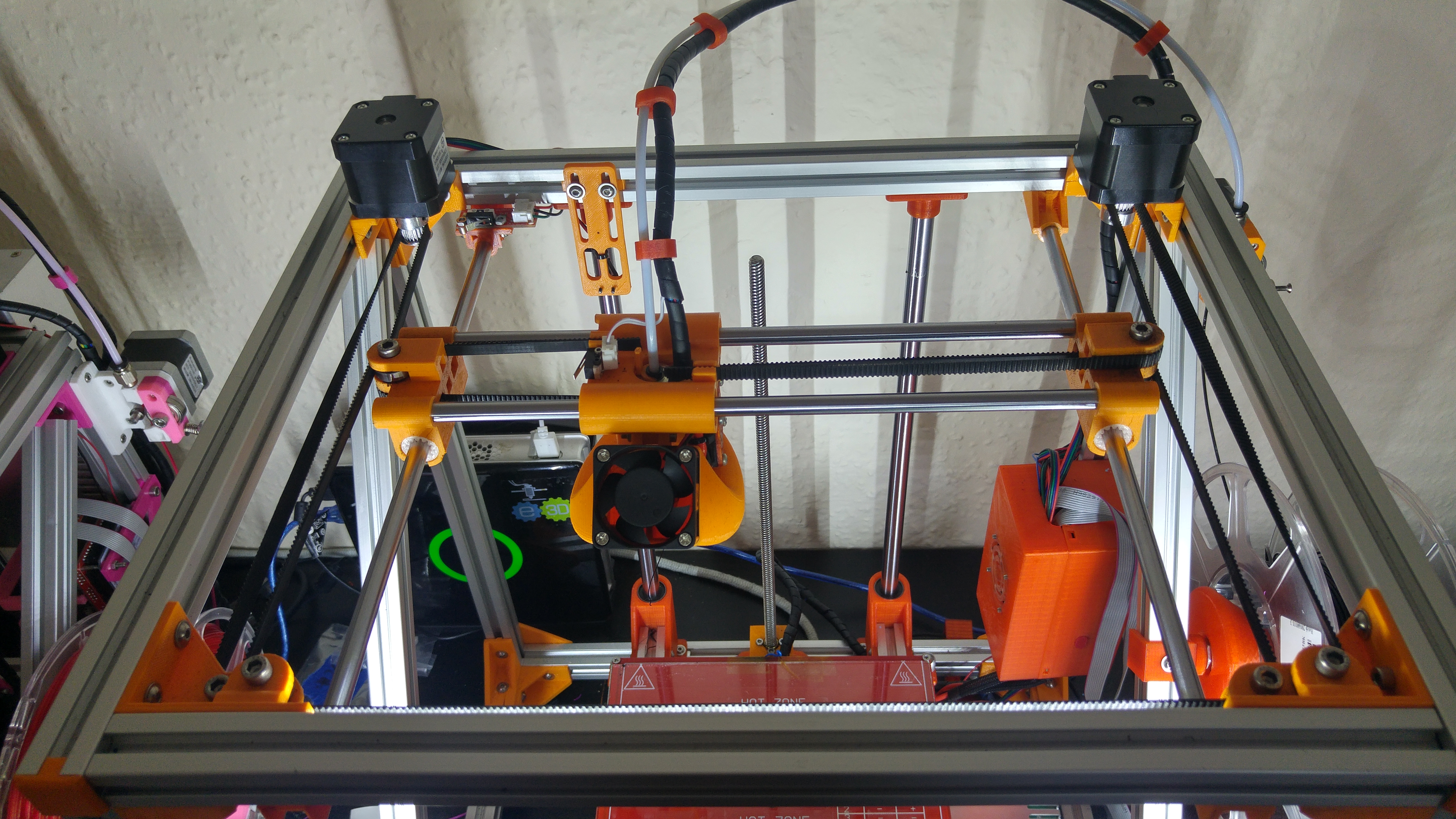
When installing the belts, pull the Carriage assembly to the front of the printer and secure with a cable tie or bind to the frame with string at both ends of the X Axis, this helps with even tensioning. Loosen off the rear 2 bolts on the motors so they pivot on the bolt that is closest to the front. Install the bottom belt first and tension by rotating the motor back into position and tightening the bolts. It does not need to be highly tensioned, just enough so it is decently tensioned. Repeat this with the top belt making sure tension is as even as possible on the belts.
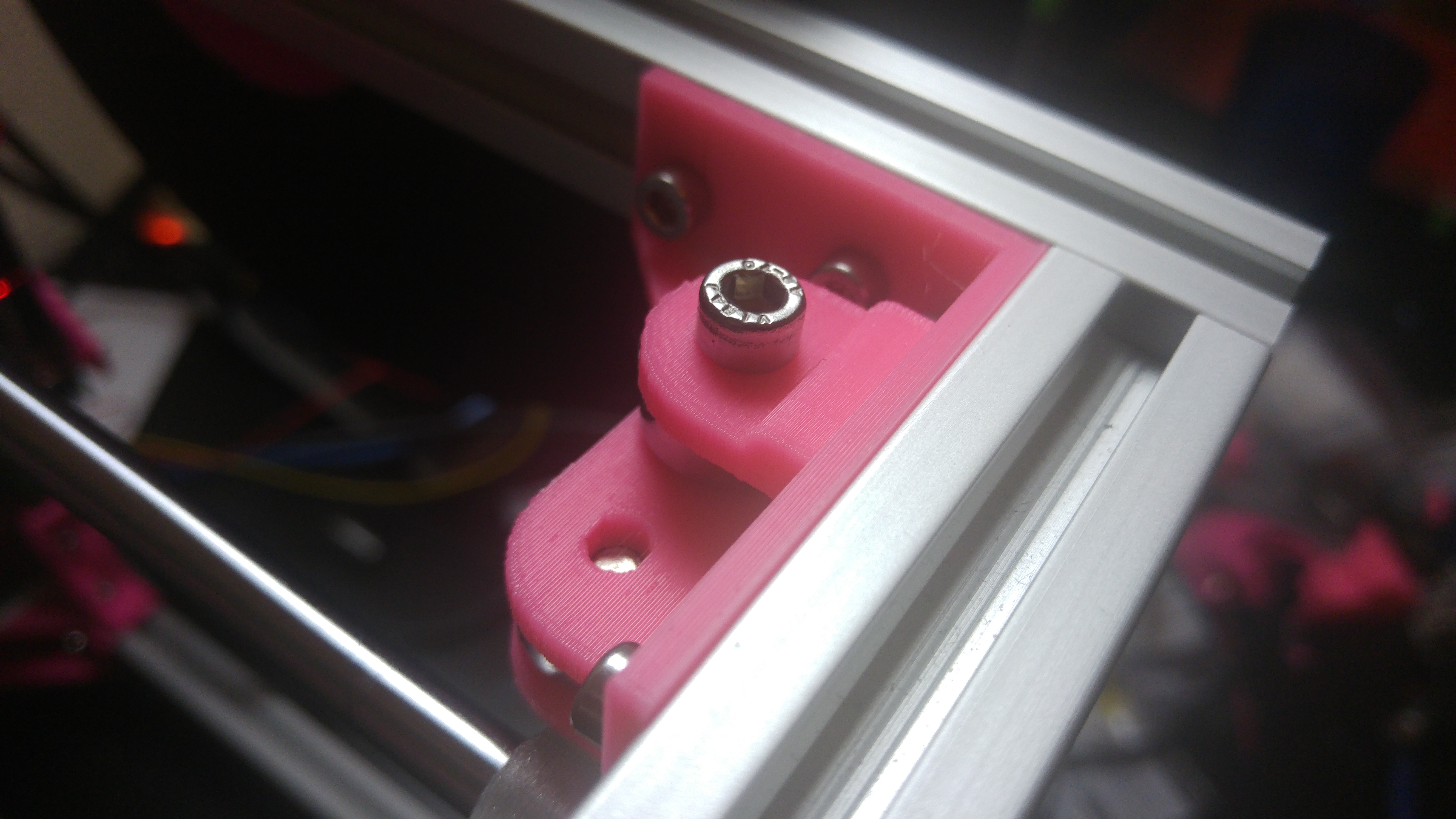
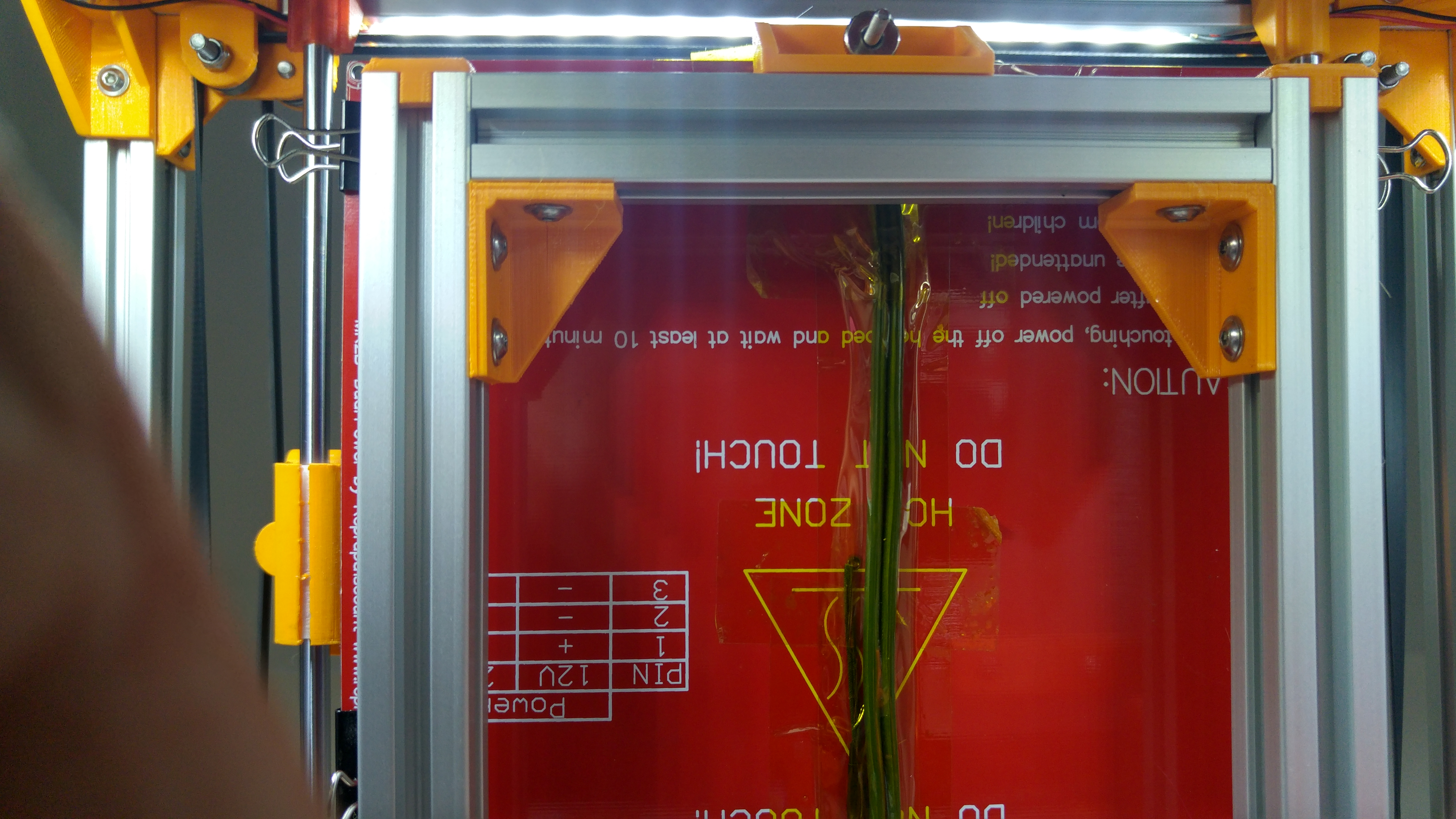
Install the Z Endstop with drop in T Nuts over the left hand Z bed mount as seen in the above images.
The Extruder assembly can be installed with Drop in or Printed T Nuts on the back right vertical extrusion on the outside, make sure this is slid to the top of the extrusion.
Image to come
Install the Hot End to the Carriage, making sure the wires go through the hole in the Carriage and the mount on the layer fan is pointing towards the front of the printer. DO NOT leave the wiring on the outside as this will crush the wires and cause issues when printing on the right hand side of the bed. Plug in / Solder the wire for the X Endstop in the NO (Normally open) position
Install the Y end stop (Makerbot style) on the Rod endstop mount, this bolts with 2 M3 x 16mm bolts with the head underneath and the nuts on the top.
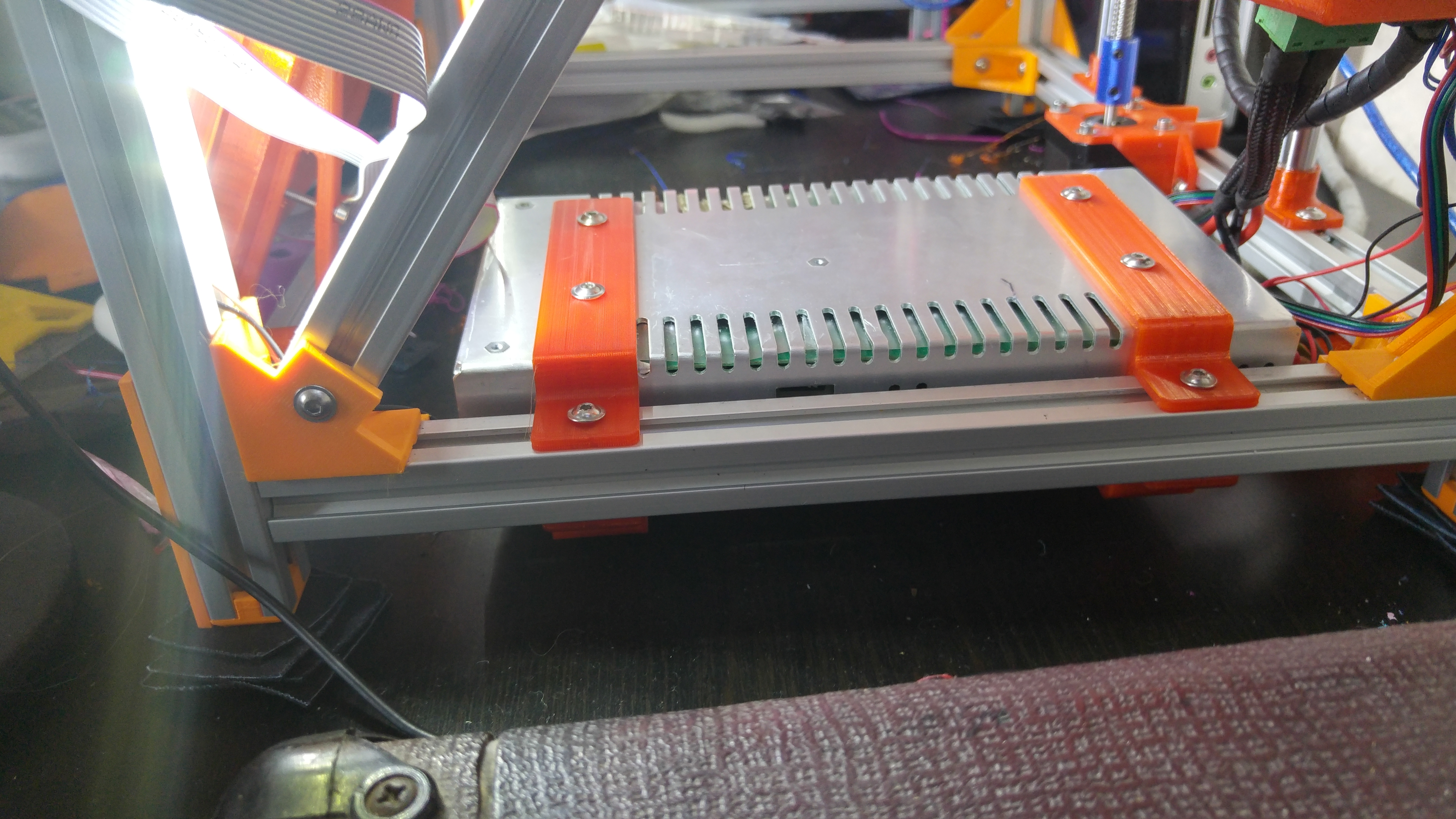
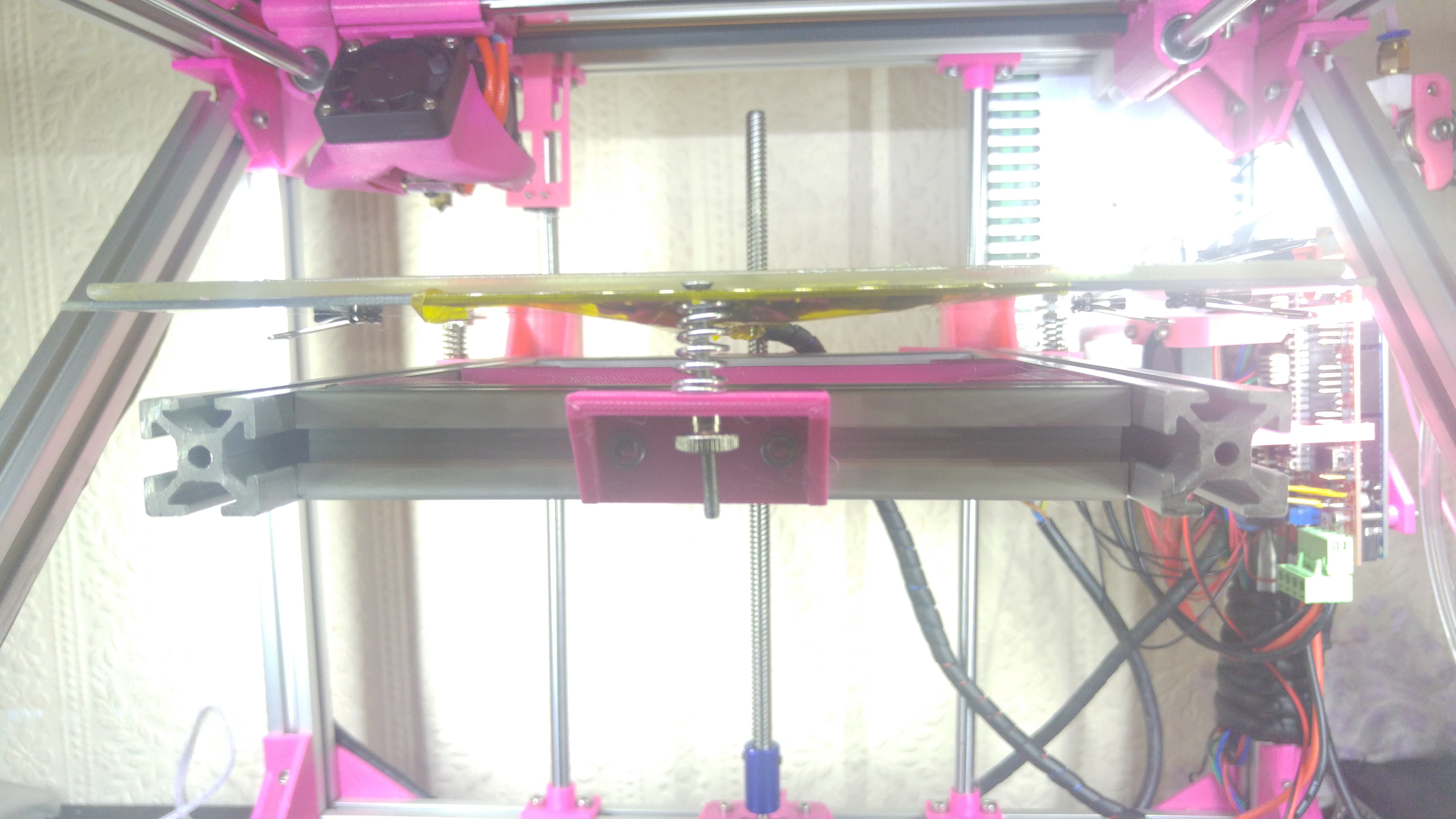
Install the bed with the soldered wiring points to the front of the Printer and the wires pointing to the back over the rear 147mm Bed Extrusion. Insert the 40mm M3 machine screws through the hole in the bed, then add the spring on the bottom and place through the mounting holes on the bed assembly. Tighten down half way with the M3 thumb nuts.
Plug in the wiring to the RAMPS as shown below:
NOTE - IMPORTANT When plugging in the Y Endstop, make sure this is plugged in correctly. Note the S, + & - marks on the board. Red wire is +, Black wire is - and the Green (usually) is S. If this is not done, you will blow the Arduino.
All Stepper wires should be the same way around with the same colour wire to the top. If you find the steppers rotate in the wrong direction, flip the plugs so that wire is at the bottom. If using Stepper motors from E3D the Black wire should be at the top, facing the extruder and blue should be at the bottom facing the Power supply

Mount the RAMPS box to the frame with Printed T Nuts under the Extruder, making sure there is enough space to get the USB cable in.
Mount the PSU to the frame, with printed or drop in T Nuts if you've not done so yet and connect the small fan from the Hot End and the Fan from the RAMPS box to the PSU along with the 14 AWG wire to connect the RAMPS to the PSU.
(optional) Connect the Screen to the RAMPS if you have one. The Cables will only work one way around if you find the screen doesn't work swap the cables around.