Iris Hardware Guide
- Introduction
- Basic Components
- Possible Add-Ons
- Building the Robot
- Build the Robot to the Appropriate Height
- Mount the Laptop Box
- Mount the Tablet and Webcam
- Connect the Components
- Add the Banner Costume
- Current Challenges/Future Improvements
Iris is a low-cost open hardware/open software telemedical robot platform. We designed Iris to be easily customizable to different clinical contexts so others can adapt the system to their own local needs.
We developed Iris using low-cost hardware from our lab. We provide the specifications here, though many components can be interchanged with different alternatives. Additionally, the system can be customized for different needs (e.g., adding a light that can be turned on and off for pupillary response tests).
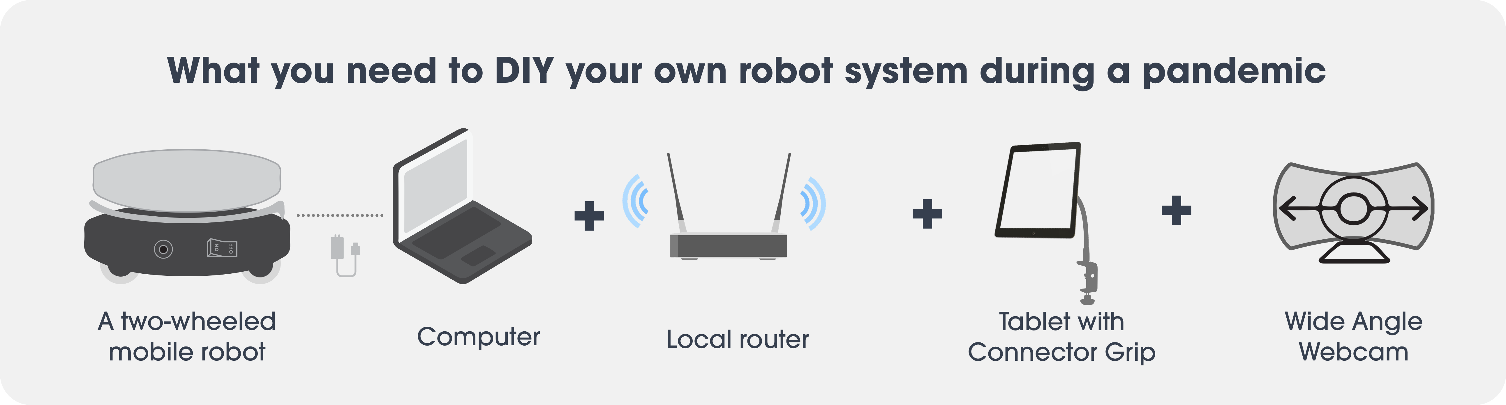
Fig. 1 The basic hardware components of Iris, including a two-wheeled mobile robot with a computer, a local router, a tablet, and a wide-angle camera mounted four feet high on the robot.
Iris's basic components are shown in Fig. 1. It consists of a two-wheeled mobile robot base with a computer, a local router, tablets with a mount, and a wide angle camera with a mount. It is helpful if the tablet of the robot (e.g., the remote user's "head") is at the height of the person interacting with the robot (e.g., a patient) to enable the interactant to see the operator's face and to enable the operator to easily see the interactant.
This table shows each of the components, their motivation, and the specific hardware we used (as of 2020).
| Component | Required/Optional | Estimated Cost (as of 2020) | Why Needed | What We Used |
|---|---|---|---|---|
| Two-wheeled mobile robot + structure to make the robot taller | Required | $700 | Mobility | Turtlebot 2 with a Kobuki base + platforms to make the robot taller (link) |
| Depth sensor | Optional | $150 | Mapping and autonomous navigation | Astra Pro depth sensor (not yet implemented) (link) |
| Computer running Ubuntu 18.04 with ROS Melodic | Required | $380 | Running the robot base | Lenovo ThinkPad 11e running Ubuntu 18.04 with ROS Melodic (link) |
| Portable router | Required | $62 | 1) In case your robot will be somewhere without internet access or 2) you prefer to keep your robot on a private network to help improve security | GL-AR750S-Ext portable router (link) |
| Control tablet | Required |
|
Control the robot through the interface | Samsung Galaxy Tab A (link) |
| Tablet case | Required | ~$20 | Protect the tablet | Durable case on Amazon.com |
| Tablets for video call | Optional | Varies | Communicate with the interactants | Provided by our emergency department (control tablet may double as one of these) |
| Tablet mount | Required | $35 | Hold the tablet | Arkon TAB188L22 tablet mount (link) |
| Wide angle webcam | Required | ~$30 | Provide video and situational awareness to operator | 1080p wide angle webcam on Amazon.com |
| Webcam mount | Required | $21 | Hold the webcam | Acetaken C920WM-001 webcam wall mount (link) |
| Nuts/bolts/washers for mounting | Required | ~$5-10 | Mount everything to the robot | M4 hex nuts/bolts/washers |
| Laminated instruction cards | Optional | ~$5-10 | Provide instructions for robot use and cleaning | Laminated printed paper cards |
| Plastic resin box | Optional | ~$4/box | Secure and protect the laptop | Whitmore plastic document boxes (link) |
| Laminate | Optional | ~$0.19/sheet | Make the Turtlebot platforms easier to clean by covering holes | Amazon Basics plastic laminating sheets (link) |
| Costume | Optional | ~$37 | Convey robot's purpose to interactants and bystanders | Printed vinyl banner (link) |
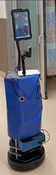
Fig. 2 Iris robot with banner and laptop in the box.
Beyond the basic components listed above, we added a few extra components. We printed a vinyl banner and secured it around the robot with zip ties (see Fig. 2). We designed the banner to look like scrubs, with a stethoscope on the front. We printed "Tele-Medicine Robot" in large letters across the back, along with the UCSD Health Systems logo and our lab logo, to make the purpose of the robot clear (Fig. 3).
We ordered the banner from 48HourPrint.com. The banner's dimensions were 38"x22".

Fig. 3 Image for the banner we made for Iris. We designed the banner to have a stethoscope and to look similar to the scrubs healthcare workers in our emergency department wear to indicate to patients what the robot's purpose was. We also wrote "Tele-Medicine Robot" in large letters on the back to indicate its purpose.
Furthermore, we attached laminated cards with basic start-up and shut-down procedures and cleaning procedures, so users would have easy access to instructions if they were unfamiliar with the system or forgot how to do something.
We also put the laptop in a plastic resin box lined with foam (except where the laptop vents were located) with cut-outs for the necessary ports. The box also held the portable router and a USB hub we used, since our laptop did not have as many USB ports as we needed. This made the system easier to clean and enabled us to secure the laptop on the robot by mounting the box with bolts.
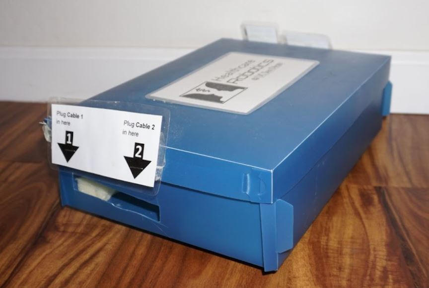
Fig. 4 The plastic resin box we used to house the laptop. Laminated cards instructed clinicians where to plug things in.
We put laminate over the Turtlebot platforms to cover the small holes in them. The infection control department at our hospital suggested we do this to make the robot easier to clean.
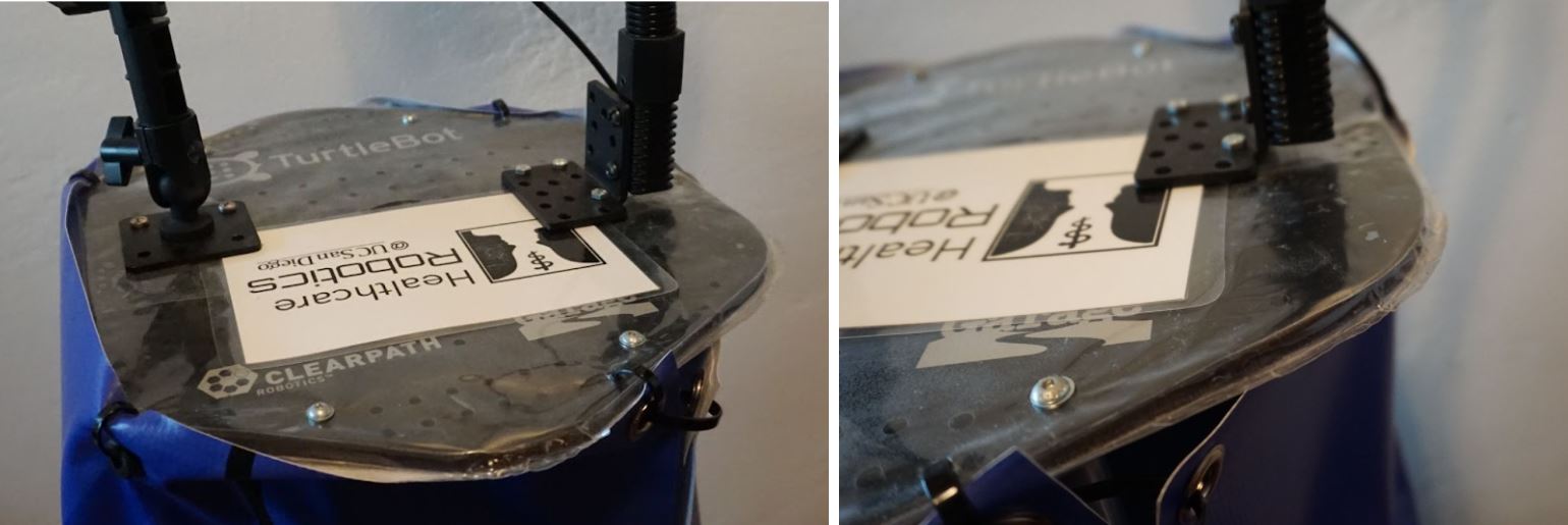
Fig. 5 We laminated the Turtlebot platforms to make cleaning the robot easier.
While we did not use this in our study, we also mounted a Asus Xtion Pro depth sensor near the base of the robot. In the future, we plan to use this to help localize the robot so we can show a map with the robot's location on the interface. It also could be used to assist users in avoiding obstacles or for autonomous navigation.
These instructions assume you are using the same components we did.
Use extra (possibly laminated) Turtlebot platforms and aluminum rods to build the robot up to the approximate height of beds in your hospital. Note that if you make it too tall, it may become unstable and more likely to tip over. Our highest platform was approximately 30 inches high.
If using laminated platforms, you will need to cut the laminate over the holes in the platform where you want to mount other components, such as the webcam and tablet. Simply cutting a small "X" in the laminate should be sufficient.
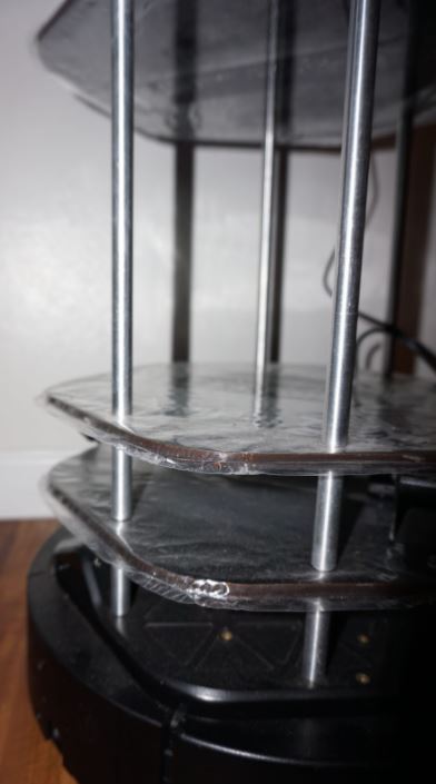
Fig. 6 Use the Turtlebot poles and (laminated) platforms to build up the robot to the appropriate height.
If using a box to hold the laptop, cut holes in the bottom that align with holes in the Turtlebot platform where you will mount it. We recommend mounting it on one of the bottom platforms to make the robot more stable. The more weight there is towards the top of the robot, the easier it will be to tip it over.
Also cut holes in the sides of the box that align with the laptop ports (including USB ports, the charging port, power button, etc.). We needed to use a USB hub, so we cut an extra hole in the side of the box to enable us to feed cords to the hub. Cut a hole in the back or bottom of the box where the laptop vent is.
Mount the box to the Turtlebot platform with M4 nuts, bolts, and washers. You may also glue some foam or other material to the box to give the laptop some padding, but make sure not to block the laptop's vents.
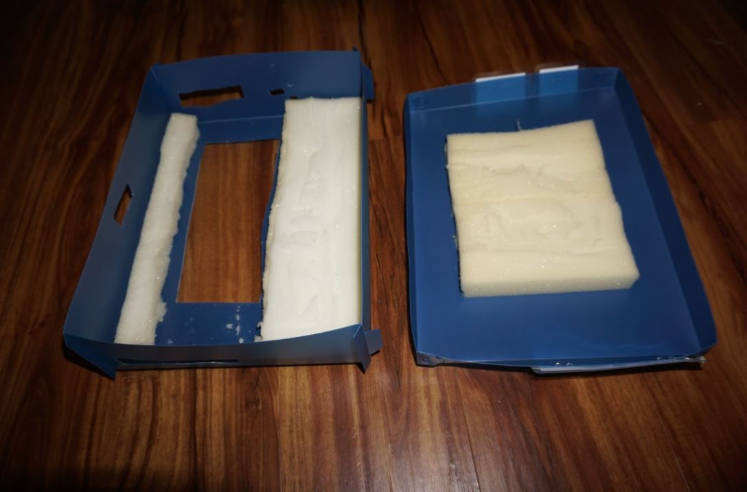
Fig. 7 Plastic resin box with foam for padding and holes cut for laptop ports and vents.
Mount the tablet and webcam mounts to the top Turtlebot platform with M4 nuts, bolts, and washers. We mounted the tablet towards the back of the platform and the webcam near the front. Note that the mounting holes may not all align with the holes in the Turtlebot platforms, but you should be able to get at least two to align. Both mounts we used can be adjusted to optimize the angle of the webcam and tablet for different purposes.
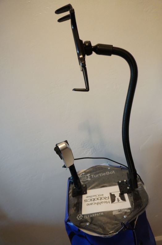
Fig. 8 We put the camera mount near the front of the robot and the tablet mount near the back.
Place the laptop in the box and plug in the Turtlebot base and webcam cords to the appropriate ports. Plug in the portable router (to power it) and place it in the box along with the laptop.
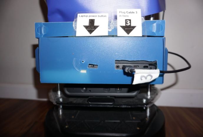
Fig. 9 Connect components. We also added labels on the cords to clearly indicate which port each cable should be plugged into.
If using a banner to indicate the robot's purpose, wrap the banner around the Turtlebot platforms and secure it with grommets and zip ties.
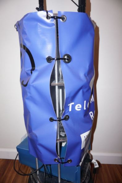
Fig. 10 We used grommets and zip ties to secure the banner to the robot.
Using a local router that is not connected to the internet makes the connection more secure and helps protect patient privacy. However, the local router signal is somewhat limited. In our ED, the signal still worked about 20-30 feet away from the operator, around a corner and through a door. However, beyond this, the signal deteriorated, and the controls became very laggy, making it difficult to control the robot. We are exploring other options for future deployments, such as integrating the robot into the hospital's existing WiFi infrastructure, to enable Iris to be operated from further away.