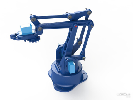
This project aims to use the open source robot manipulator EEZYbot MK1 of daGHIZmo with computer vision. A first part will be conducted in order to simply manipulate it with a joystick and then we will add the computer vision so that to end effector can follow an object.
The MK1 is a 3D printed robot manipulator that can be quite easily be assemble and cheaper so that why it was choosed for this project. It uses 4 SG90 servos and can be controlled from an arduino uno. The model and the assembly steps can be found here: EEEZYbot MK1
The robot arm has 4 DOF: waist/base, shoulder, elbow and gripper. In software, these are referred to as base/BS, upDown/UD, frontBack/FB and gripper/GR respectively.
The inverse kinematic allows to manipulate of robot for (x,y) coordinates. For a position you have to calculate the joints angles that your robot needs to have in order to reach that position, that what the equation of the inverse kinematic translates. For now the inverse kinematic used in the one describe here Inverse Kinematic arduino. You can find the inverse kinematic in the program Joystick.ino.
In order to manipulate the MK1 we used an arduino uno and a joystick as you can see on the following picture:
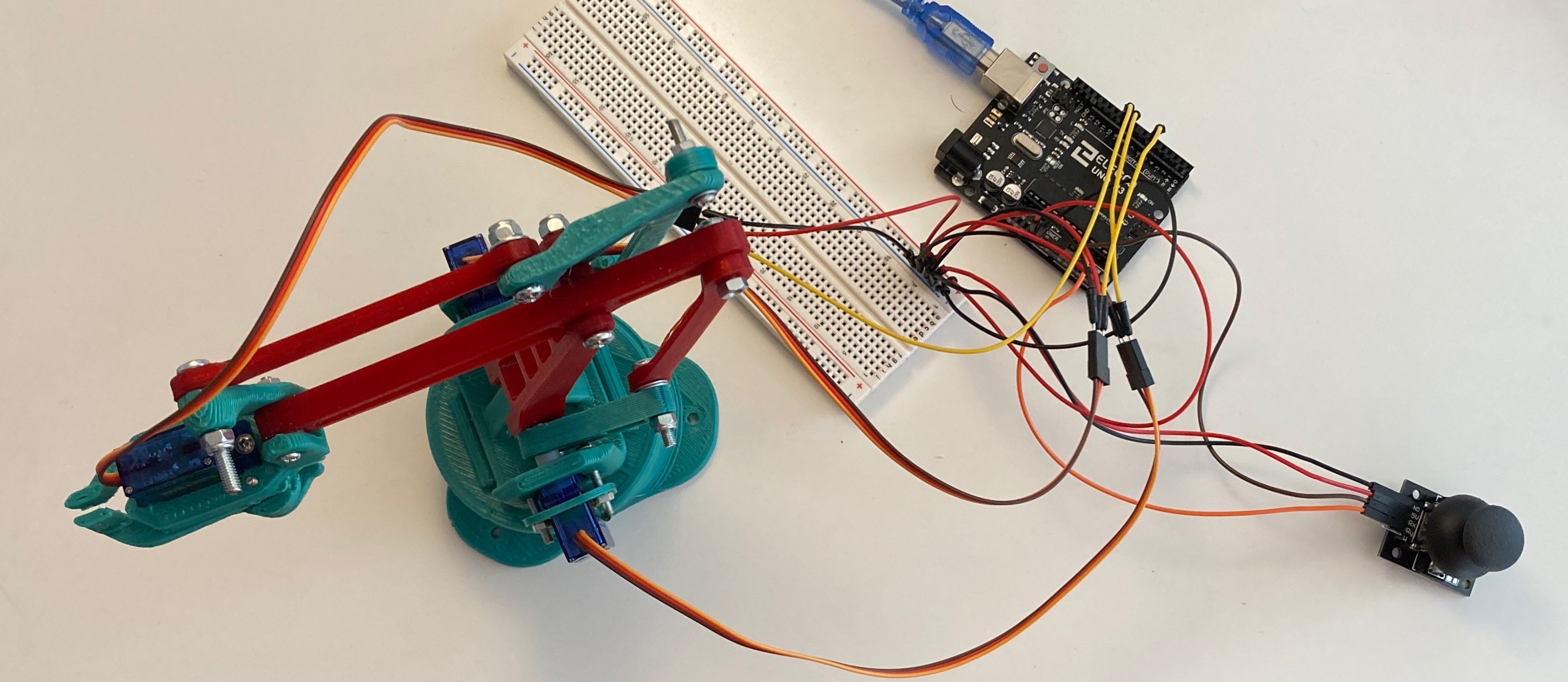
The servos are plugged on the PWN pins 5, 6, 9. And the joystick is plugged on the A0 and A1.
First of all we want to measure the position of an object on the table. For that task we are using OpenCV.
You have to check the configuration, you should have the same versions as below or later.
$ pip list | grep -e opencv -e numpy
numpy                    1.17.5
opencv-contrib-python    4.1.2.30
opencv-python            4.1.2.30
We start with the importations:
import cv2
import numpy as np
We will print 4 aruco markers from 0 to 3 from the calibration:
aruco = cv2.aruco
p_dict = aruco.getPredefinedDictionary(aruco.DICT_4X4_50)
marker =  [0] * 4 #Initialisation
for i in range(len(marker)):
  marker[i] = aruco.drawMarker(p_dict, i, 75) # 75x75 px
  cv2.imwrite(f'marker{i}.png', marker[i])
The execution of this code should produce 4 file "marker0.png " to "marker3.png " that you will print and place in order to make a square of 15cm.
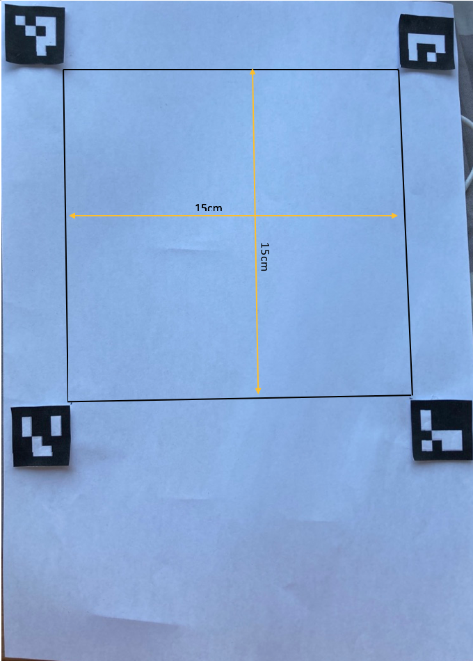
We take a picture of your aruco markers and the object you want to localize, you rename it "inu.jpg":
This part of the program will transform you picture on a top view.
aruco = cv2.aruco
p_dict = aruco.getPredefinedDictionary(aruco.DICT_4X4_50)
img = cv2.imread('inu.jpg')
corners, ids, rejectedImgPoints = aruco.detectMarkers(img, p_dict) #detection

#Change here
corners2 = [np.empty((1,4,2))]*4
for i,c in zip(ids.ravel(), corners):
  corners2[i] = c.copy()
marker[0] = corners2[0][0][2]
marker[1] = corners2[1][0][3]
marker[2] = corners2[2][0][0]
marker[3] = corners2[3][0][1]

width, height = (500,500) #Size of the image after transformation
marker_coordinates = np.float32(m)
true_coordinates   = np.float32([[0,0],[width,0],[width,height],[0,height]])
trans_mat = cv2.getPerspectiveTransform(marker_coordinates,true_coordinates)
img_trans = cv2.warpPerspective(img,trans_mat,(width, height))
cv2.imshow("sample",img_trans)
cv2.waitKey(5000)
This is the result you should obtain:
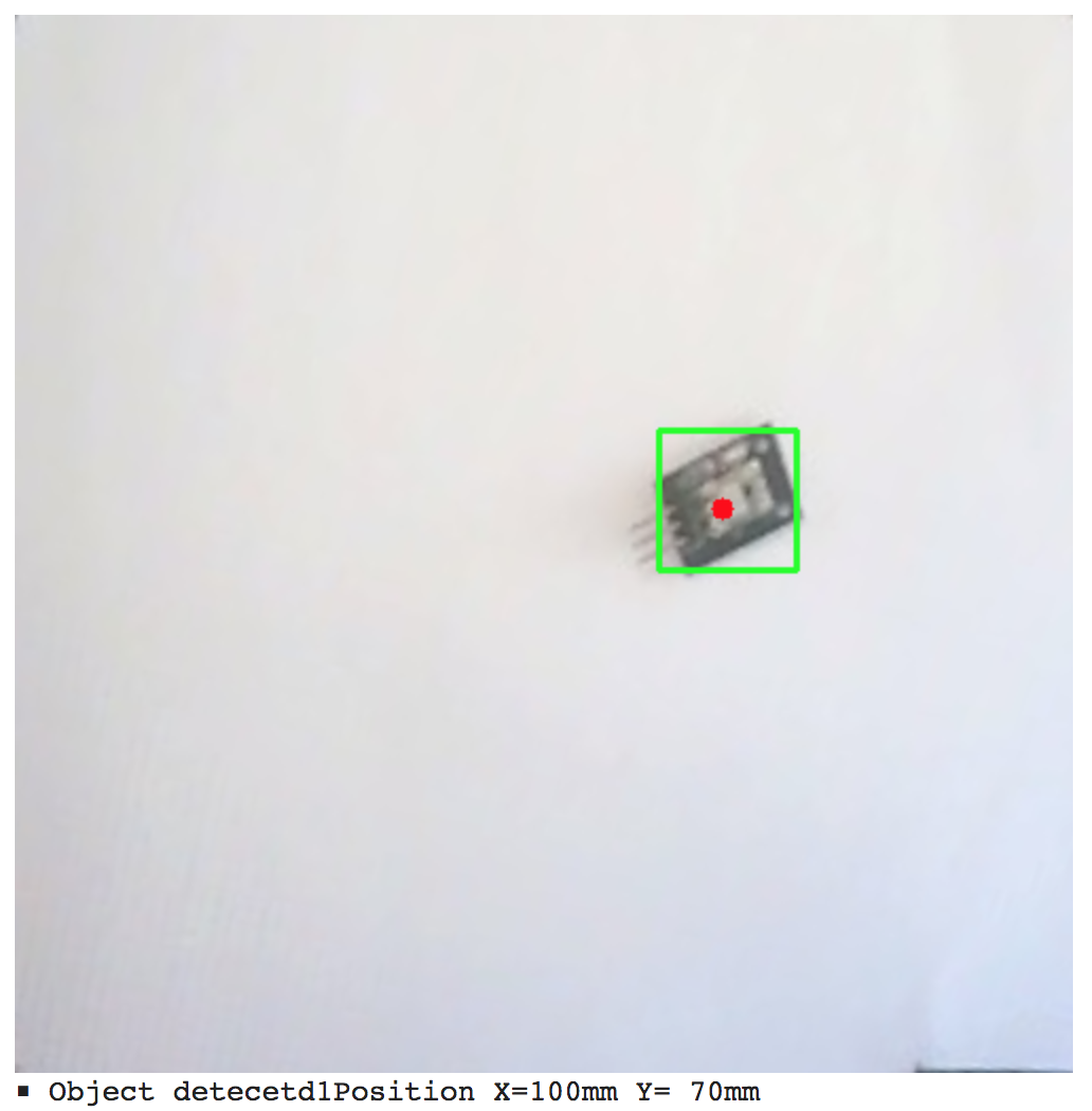
Finally this part will give you th position of the object on the picture:
tmp = img_trans.copy()

# Conversion of the gray scale
tmp = cv2.cvtColor(tmp, cv2.COLOR_BGR2GRAY)
#cv2_imshow(tmp)

# Treatment of the blur
tmp = cv2.GaussianBlur(tmp, (11, 11), 0)
#cv2_imshow(tmp)

# (3)Binarisation Processus
th = 130 #Seuil de binarisation(Ajustement requis)
_,tmp = cv2.threshold(tmp,th,255,cv2.THRESH_BINARY_INV)
#cv2_imshow(tmp)

# (4)Blob detection (= mass)
n, img_label, data, center = cv2.connectedComponentsWithStats(tmp)

# (5)Organisation of the detection results
detected_obj = list() #Destination de stockage du résultat de la détection
tr_x = lambda x : x * 150 / 500 #Coordonnées de l'image sur l'axe X → coordonnées réelles
tr_y = lambda y : y * 150 / 500 #Axe Y 〃
img_trans_marked = img_trans.copy()
for i in range(1,n):
  x, y, w, h, size = data[i]
  if size < 300 : #Ignore the area with less than 300 pixels
    continue
  detected_obj.append( dict( x = tr_x(x),
                              y = tr_y(y),
                              w = tr_x(w),
                              h = tr_y(h),
                              cx = tr_x(center[i][0]),
                              cy = tr_y(center[i][1])))
  #Verification
  cv2.rectangle(img_trans_marked, (x,y), (x+w,y+h),(0,255,0),2)
  cv2.circle(img_trans_marked, (int(center[i][0]),int(center[i][1])),5,(0,0,255),-1)

# (6)Show the results
cv2.imshow("sample",img_trans_marked)
cv2.waitKey(5000)
for i, obj in enumerate(detected_obj,1) :
  print(f'■ Object detected{i}Position X={obj["cx"]:>3.0f}mm Y={obj["cy"]:>3.0f}mm ')
And the final result should be as followed with the coordinates of the object: