
PSX SIO-qsb is a quick solder board (QSB) developed specifically for use with the PSIO* optical drive emulator for the original PlayStation (PS1).
The typical PSIO installation requires a standard Switch Board with nine wires soldered to specific points on the mainboard, along with some trace modifications.
As a more practical alternative, PSX SIO-qsb connects directly to the parallel interface on the underside, reducing the wiring to only four connections.
It features the most compact footprint and a cleaner layout, enabling a more efficient and discreet installation.
* PSIO is a flash cartridge that allows games to be loaded directly from an SD card via the console’s rear Parallel I/O port, bypassing the optical drive entirely.
- Pinout
- Installation Notes
- Bill of Materials (BOM)
- Adapter Layout
- Schematic
- Gallery
- Why is it called PSX SIO-qsb?
PSX SIO-qsb is a Quick Solder Board (QSB) developed as an alternative to the standard PSIO Switch Board, offering a simplified installation process with a more streamlined and purposeful layout.
It maintains full compatibility with PSIO cartridges while focusing on clear routing and practical integration.
Designed for reduced board area and tidy wiring, the QSB can be fabricated using standard FR-4 PCBs (1 mm or thinner) or Flex PCBs for ultra-low profile installation.

By reducing the number of external wires compared to the standard Switch Board, this board simplifies installation without compromising PSIO functionality.
| Signal | Function | Routed to Mainboard | Pin(s) on Connector | Description |
|---|---|---|---|---|
| XI | CD_INT | Yes | Wired | Interrupt from CD-ROM |
| XE | CD_CS | Yes | Wired | Chip Select for CD-ROM |
| CI | CPU_INT | Yes | Wired | Interrupt to CPU |
| CE | CPU_CS | Yes | Wired | Chip Select to CPU |
| EN | CART_IN | No | 05 | Slot-detected cartridge in |
| PI | PSIO_INT | No | 31 | PSIO interrupt signal |
| PE | CPU_CS | No | 65 | Shared with CE |
| VDD | +3.3V | No | 17, 51 | Supplied from CN103 |
| VSS | GND | No | 1, 34, 35, 68 | Ground via CN103 |
Note
- The four primary signal lines XI, XE, CI, CE must be manually wired from their corresponding pads on the PSX SIO-qsb to specific solder points on the PS1 mainboard.
- The remaining lines VCC, VSS, EN, PI, and PE are soldered directly to the through-hole pins of the CN103 (Parallel I/O port), located on the underside of the PS1 mainboard. Their corresponding pads on the PSX SIO-qsb are designed to align precisely with these pins for direct soldering to the exposed pin leads.
- Preparation of the console’s mainboard and proper installation of the switchboard are strictly required for PSIO operation.
- Connections should be soldered directly to the designated points previously prepared on the mainboard.
- The recommended wire for these connections is 30 AWG wire-wrap, which offers the ideal flexibility and diameter for clean routing.
- Fine-pitch soldering skills and proper tools are strongly recommended.
- The console’s CD-ROM bay remains fully functional when the PSIO cartridge is disconnected, as with the standard Switch Board design.
- Installing the PSX SIO-qsb does not interfere with the normal operation of the CD-ROM drive when the PSIO cartridge is not inserted.
- When using the PSIO menu system, users may launch disc-based games directly from the CD-ROM drive or access the built-in CD Player without removing the PSIO cartridge.
Important
Installation points differs depending on PS1 motherboard revision. Always reference an installation diagram for your console’s PU-xx board code.
Caution
Never insert the PSIO cartridge into a console that has not been modified with the switchboard, as doing so may result in damage to both the PSIO and the console’s mainboard.
| Reference | Value | Package | Description |
|---|---|---|---|
| R1, R2, R3 | 10k | 0603 SMD | Thick Film Resistor |
| R4 | 47k | 0603 SMD | Thick Film Resistor |
| C1 | 100nF | 0603 SMD | Multilayer Ceramic Capacitor (MLCC) |
| U1 | 74HC4066 | TSSOP-14 | Quad SPST Analog Switch (Nexperia or compatible) |
A ready-to-manufacture Gerber file for the PSX SIO-qsb is included in this repository and can be downloaded from the Releases section:
- PSX SIO-qsb: Manufacturing-ready layout for a low-profile add-on under the CN103 interface
Tip
Recommended PCB material: FR-4 Standard (thickness ≤ 1.0 mm) or Flex PCB, to fit beneath the mainboard.
For prototyping and production of the PSX SIO-qsb, we recommend JLCPCB as the preferred manufacturing partner.
Their consistent quality, competitive pricing, and fast turnaround make them an ideal choice for hobbyists and professionals alike.

Founded in 2006, JLCPCB is one of the world’s leading PCB and PCBA manufacturers, serving over 6 million customers across 180+ countries.
Their fully automated production lines and digital ordering platform enable rapid delivery of high-reliability boards at low cost, ideal for prototyping and small-batch runs.
Note
The PSX SIO-qsb was prototyped and validated using FR-4 PCBs manufactured by JLCPCB.
- Base Material: FR-4
- PCB Thickness: 0.8 mm
- Surface Finish: HASL
- Layers: 2
- PCB Assembly: Top side
JLCPCB frequently offers discount coupons and promotional pricing, making it a cost-effective option even for small quantities.
Manufacturing and shipping times are impressively fast, with most orders processed and dispatched within a few business days.
Schematic and PCB - Click to expand
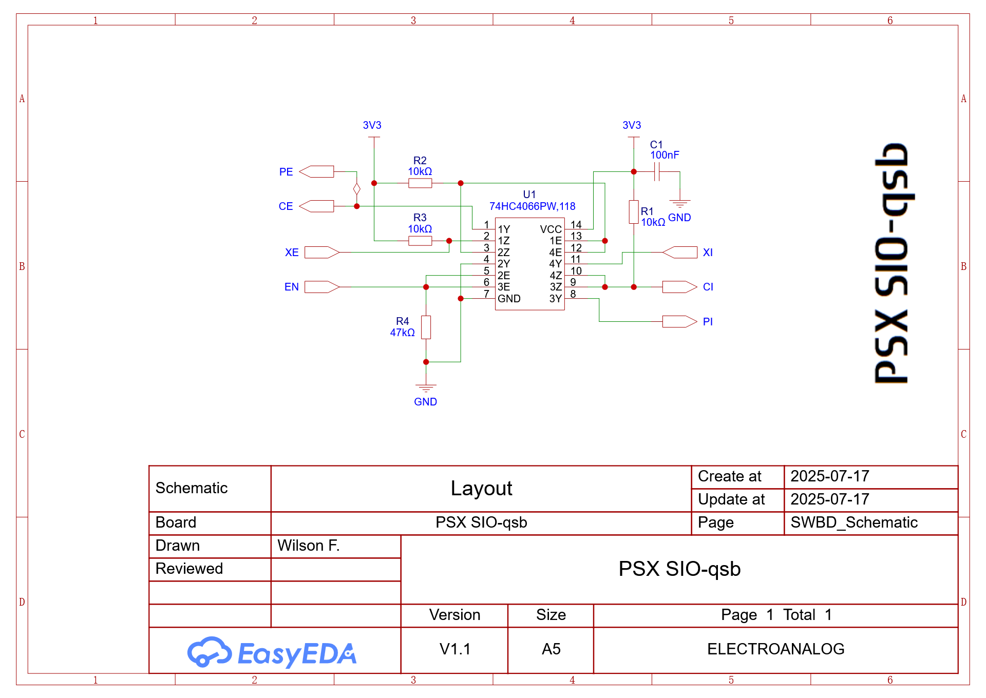 PSX SIO-qsb Schematic |
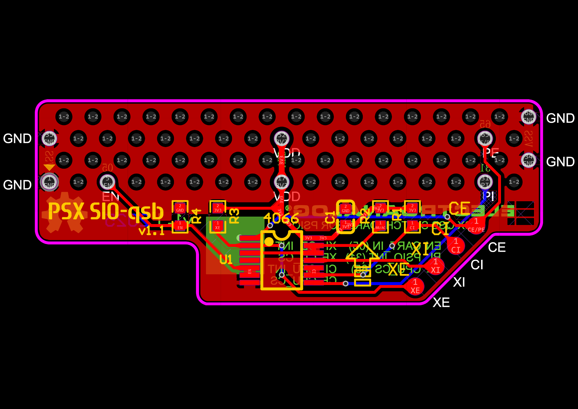 PSX SIO-qsb PCB |
The PSX SIO-qsb was developed based on the original Switch Board schematic published by Cybdyn Systems, available at GamingDocs.
Its physical layout was designed from scratch using the mechanical footprint of a 68-pin SCSI connector as a baseline for proper alignment and integration under the PS1 mainboard.


PSX SIO-qsb installed over CN103 pins on PU-8 mainboard

Front view of PSX SIO-qsb

Back view of PSX SIO-qsb

PSX SIO-qsb may be considered a utilitarian name, as "qsb" clearly identifies both the form factor and function of the board.
In this case, it refers to a compact switchboard that facilitates signal routing between the PSIO and the console’s CD-ROM interface, all while preserving the simplicity of quick soldering.
The designation defines its role clearly as an essential bridge for PSIO operation, engineered to streamline installation with minimal overhead.
Yes, that’s the point. Let the name speak for itself.
This project is licensed under the CERN Open Hardware Licence Version 2 – Strongly Reciprocal (CERN-OHL-S v2).
You may copy, modify, and distribute the design files, but any modified versions must also be licensed under the same terms.
For full license text, see the LICENSE file or visit the CERN-OHL-S v2 official page.
Created by Electroanalog® VICE (2025)
Compatible with genuine and third-party PSIO cartridges.
PlayStation is a registered trademark of Sony Interactive Entertainment LLC (SIE), formerly Sony Computer Entertainment Inc. (SCE). All rights reserved.
psx playstation ps1 psio switchboard qsb modchip retrogaming