-
PROBLEM DESCRIPTIONI have an ERC-310 dimmer which works ok with TUYA MCU. Inside there is a TYWE3S module. I added an external relay on a free pin and selected relay on the tasmota menu on that pin. Oddly, it doesn't work. I tried every free good pin (4 5 12 13 14). They all work as switches (input) and as LEDs. So, they work as input and output as LED, but not as relay. Using the LED configuration, I can drive the external relay, but it "floats" while booting (it "blinks" 1 time like the onboard led) and while restarting/upgrading firmware (4 times in the same sequence). REQUESTED INFORMATION
  Configuration output here:
13:20:22.294 CMD: Backlog Template; Module; GPIO 255
13:20:22.366 RSL: RESULT = {"NAME":"Generic","GPIO":[1,1,1,1,1,1,1,1,1,1,1,1,1,1],"FLAG":0,"BASE":18}
13:20:22.576 RSL: RESULT = {"Module":{"54":"Tuya MCU"}}
13:20:22.829 RSL: RESULT = {"GPIO0":{"0":"None"},"GPIO1":{"2272":"Tuya Tx"},"GPIO2":{"0":"None"},"GPIO3":{"2304":"Tuya Rx"},"GPIO4":{"0":"None"},"GPIO5":{"0":"None"},"GPIO9":{"0":"None"},"GPIO10":{"0":"None"},"GPIO12":{"0":"None"},"GPIO13":{"0":"None"},"GPIO14":{"288":"Led1"},"GPIO15":{"0":"None"},"GPIO16":{"0":"None"},"GPIO17":{"0":"None"}}
13:20:24.381 RSL: STATE = {"Time":"2022-05-14T13:20:24","Uptime":"0T00:05:11","UptimeSec":311,"Heap":26,"SleepMode":"Dynamic","Sleep":50,"LoadAvg":19,"MqttCount":0,"POWER":"OFF","Wifi":{"AP":1,"SSId":"VillaTorreZisa","BSSId":"E8:DF:70:9D:6F:7B","Channel":6,"Mode":"11n","RSSI":92,"Signal":-54,"LinkCount":1,"Downtime":"0T00:00:05"}}
Rules output here:
  STATUS 0 output here:
13:22:17.404 CMD: Status 0
13:22:17.409 RSL: STATUS = {"Status":{"Module":54,"DeviceName":"Tasmota","FriendlyName":["Tasmota"],"Topic":"tasmota_434E14","ButtonTopic":"0","Power":0,"PowerOnState":3,"LedState":1,"LedMask":"FFFF","SaveData":1,"SaveState":1,"SwitchTopic":"0","SwitchMode":[0,0,0,0,0,0,0,0],"ButtonRetain":0,"SwitchRetain":0,"SensorRetain":0,"PowerRetain":0,"InfoRetain":0,"StateRetain":0}}
13:22:17.414 RSL: STATUS1 = {"StatusPRM":{"Baudrate":9600,"SerialConfig":"8N1","GroupTopic":"tasmotas","OtaUrl":"http://ota.tasmota.com/tasmota/release/tasmota.bin.gz","RestartReason":"Software/System restart","Uptime":"0T00:07:04","StartupUTC":"2022-05-14T12:15:13","Sleep":50,"CfgHolder":4617,"BootCount":30,"BCResetTime":"2022-05-14T11:10:08","SaveCount":279,"SaveAddress":"F6000"}}
13:22:17.417 RSL: STATUS2 = {"StatusFWR":{"Version":"11.1.0(tasmota)","BuildDateTime":"2022-04-13T06:40:42","Boot":31,"Core":"2_7_4_9","SDK":"2.2.2-dev(38a443e)","CpuFrequency":80,"Hardware":"ESP8266EX","CR":"372/699"}}
13:22:17.421 RSL: STATUS3 = {"StatusLOG":{"SerialLog":0,"WebLog":2,"MqttLog":0,"SysLog":0,"LogHost":"","LogPort":514,"SSId":["VillaTorreZisa",""],"TelePeriod":300,"Resolution":"558180C0","SetOption":["00008009","2805C80001000600003C5A0A190000000000","00000080","00006000","00004000"]}}
13:22:17.432 RSL: STATUS4 = {"StatusMEM":{"ProgramSize":626,"Free":376,"Heap":26,"ProgramFlashSize":1024,"FlashSize":2048,"FlashChipId":"1540C8","FlashFrequency":40,"FlashMode":3,"Features":["00000809","8FDAC787","04368001","000000CF","010013C0","C000F981","00004004","00001000","04000020"],"Drivers":"1,2,3,4,5,6,7,8,9,10,12,16,18,19,20,21,22,24,26,27,29,30,35,37,45,56,62","Sensors":"1,2,3,4,5,6"}}
13:22:17.438 RSL: STATUS5 = {"StatusNET":{"Hostname":"tasmota-434E14-3604","IPAddress":"192.168.178.51","Gateway":"192.168.178.1","Subnetmask":"255.255.255.0","DNSServer1":"192.168.178.1","DNSServer2":"0.0.0.0","Mac":"2C:F4:32:43:4E:14","Webserver":2,"HTTP_API":1,"WifiConfig":4,"WifiPower":17.0}}
13:22:17.442 RSL: STATUS6 = {"StatusMQT":{"MqttHost":"","MqttPort":1883,"MqttClientMask":"DVES_%06X","MqttClient":"DVES_434E14","MqttUser":"DVES_USER","MqttCount":0,"MAX_PACKET_SIZE":1200,"KEEPALIVE":30,"SOCKET_TIMEOUT":4}}
13:22:17.448 RSL: STATUS7 = {"StatusTIM":{"UTC":"2022-05-14T12:22:17","Local":"2022-05-14T13:22:17","StartDST":"2022-03-27T02:00:00","EndDST":"2022-10-30T03:00:00","Timezone":"+01:00","Sunrise":"05:09","Sunset":"20:23"}}
13:22:17.453 RSL: STATUS10 = {"StatusSNS":{"Time":"2022-05-14T13:22:17"}}
13:22:17.458 RSL: STATUS11 = {"StatusSTS":{"Time":"2022-05-14T13:22:17","Uptime":"0T00:07:04","UptimeSec":424,"Heap":26,"SleepMode":"Dynamic","Sleep":50,"LoadAvg":19,"MqttCount":0,"POWER":"OFF","Wifi":{"AP":1,"SSId":"VillaTorreZisa","BSSId":"E8:DF:70:9D:6F:7B","Channel":6,"Mode":"11n","RSSI":96,"Signal":-52,"LinkCount":1,"Downtime":"0T00:00:05"}}}
Console output here:
TO REPRODUCESteps to reproduce the behavior: EXPECTED BEHAVIOURA clear and concise description of what you expected to happen. To have a 3,3V output when selecting Relay (as when I select LED). SCREENSHOTSIf applicable, add screenshots to help explain your problem. ADDITIONAL CONTEXTAdd any other context about the problem here. (Please, remember to close the issue when the problem has been addressed) |
Beta Was this translation helpful? Give feedback.
Replies: 11 comments 2 replies
-
|
This is not an Issue with Tasmota and should have been started as a Discussion Please close and re-open as a Discussion giving detailed example of how you are connecting your relay in terms of hardware. An ESP pin is not enough to directly drive an electrimechanial relay. |
Beta Was this translation helpful? Give feedback.
-
|
It is indeed a Tasmota problem, because I am using an external power supply to drive the relay (it is a 12V relay), I used a tester (as relay there is no output and as LED there is 3,3V output as it should be) and finally because when I use the LED option, the relay works as expected (with those flickering I don't understand while restarting). Since there is no Voltage output when selecting "Relay", but there is when selecting "LED", I think it is a tasmota problem with this TYWE3S module. With a D1 mini I read the voltage both in relay and led mode while turning the gpio ON. |
Beta Was this translation helpful? Give feedback.
-
|
Your configuration above doesn't include any pin defined as Relay Please fill correctly the template so we can advise. It may be possible that when TuyaMCU is enabled, all POWER commands go to the TuyaMCU and an local relay may not be possible. But we need you to first do your homework and fll the Issue template. |
Beta Was this translation helpful? Give feedback.
-
|
this is the weblog 4 after restart 1 and LED configuration: |
Beta Was this translation helpful? Give feedback.
-
|
Configuration log with relay option: 13:47:43.962 CMD: Backlog Template; Module; GPIO 255 and weblog 4 with relay option after restart 1 00:00:00.001 HDW: ESP8266EX |
Beta Was this translation helpful? Give feedback.
-
|
When you get a device with the affliction of a TuyaMCU, you do indeed not get to have other pins act as they would without the device being managed by the other MCU, with the ESP chip merely being a "wifi modem". What you try to do is not supported by Tasmota, which is no issue, as in Tasmota not doing what it should. I think that someone had success in a similar situation configuring the intended relay pin as a PWM, and using it with a 100% duty cycle. |
Beta Was this translation helpful? Give feedback.
-
|
but the gpios are not connected with the Tuya MCU, they are not even wired to the dimmer board. I am doing an external connection. |
Beta Was this translation helpful? Give feedback.
-
I tried this option and it actually works, but it doesn't make any sense:
In this situation, you can just select "Generic 18" template and setup your gpio as relay. It will work. I wish to use the Tuya MCU (I need the ON/OFF from the wireless momentary switches linked to the tuya dimmer) and an external relay. If I use the PWM option, I loose the wireless momentary switches triggers. I really don't get what is the software problem that doesn't make the relay work while Tuya MCU template is selected :-( |
Beta Was this translation helpful? Give feedback.
-
Yes. That's why I made a suggestion for what might work. When configuring a TuayMCU, pin config as a relay will not work. I'd not expect light control with Dimmer to work either. What I meant was as a "basic mode" PWM, using SetOption15 and the PWM command. And yes, this is no "full" solution, just a possible workaround. There is no software problem here, it is just that you'd like the software do something it is not designed for. |
Beta Was this translation helpful? Give feedback.
-
|
Thanks sfromis, you made me think to find a workaround since the normal way will not work :-) And I found it! EUREKA! Reading tasmota wiki: "By default Tasmota uses the first defined Led(i) as a device status LED. Next defined LED is the power status LED which displays the status of any Relay (or other power output). When only Led1(i) is defined it serves both purposes." So, my LED wired to the relay was "blinking" as any other led during tasmota boots. Workaround:
And finally the external relay works in sync with the tuya dimmer controlled by the linked momentary push switches. The dimmer was a pain in the ass, I was not able to find any 220V led bulb working correctly with the dimmer, so I switched to on/off relay. |
Beta Was this translation helpful? Give feedback.
-
|
This is absurd - but it works. I had the exact same problem. Thanks! I have something to add, since all the buttons disappeared for my tuya floor heater panel. What worked however is to have defined two LEDs like you did, LED2 on the actual GPIO (14) for the relay and add one relay for some random GPIO (0) and now add the rule: For me it is power3 because I think tuya reserves power1 and 2 for heater and keylock.
|

Beta Was this translation helpful? Give feedback.
-
|
I am glad you solved it. I switched my dimmers to on/off this way. They work fine since then |
Beta Was this translation helpful? Give feedback.
-
|
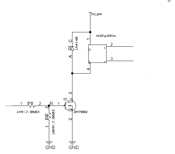
If anyone is interested, this is the circuit to drive an external relay and an external power supply. Can be any voltage. |
Beta Was this translation helpful? Give feedback.
Thanks sfromis, you made me think to find a workaround since the normal way will not work :-) And I found it! EUREKA!
Reading tasmota wiki: "By default Tasmota uses the first defined Led(i) as a device status LED. Next defined LED is the power status LED which displays the status of any Relay (or other power output). When only Led1(i) is defined it serves both purposes."
So, my LED wired to the relay was "blinking" as any other led during tasmota boots. Workaround: